


Guardian Telecom Inc.
Installation and Operation
Model HR70
Page 7
Field Repairs
Note: The only field repair permitted is to change the Tone/Pulse setting and
the replacement of fuses. All other repairs or alterations must be carried out by
Guardian Telecom or an Authorized Service Depot. See Warranty and
Disclaimer for details.
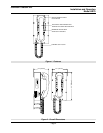
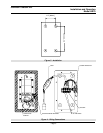
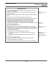
See: Figure 4 - Wiring
Connections
Fuse Replacement
• Disconnect the telephone from Tip and Ring power supplied by the PABX or
central office before attempting to replace the fuse.
• Carefully remove the front cover assembly and separate from the housing
by disconnecting the harness plugs. NOTE that the handset and all
electronics are attached to the front plate.
See: Figure 4 - Wiring
Connections
• Replace fuse in fuse holder with a 0.25 amp 250V 3AG fast blow fuse.
• Carefully replace the front plate and install all eight screws. Do not over
tighten the cover screws, there is a flexible gasket between the cover and
the body. Excessive tightening of the screws deforms the gasket and
reduces the weather resistance of the set.
WARNING!
• Replace only with a 0.25 amp 250V 3AG fast blow fuse. Failure to do so will
void the warranty.
• If, on reconnecting power, the fuse fails, check the telephone system wiring.
The fuse protects the Tip and Ring line from the telephone system. It is
usually powered at 48 volts DC and must not be connected to 120 volts AC.