


Guardian Telecom Inc.
Installation and Operation
Model HR70
Page 6
Installing the HR70
• Follow all appropriate electrical codes and use only approved electrical
fittings for the installation.
• Choose a wall location that is free of obstructions and permits space for ½”
NPT conduit runs.
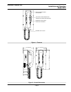
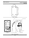
See: Figure 2 - Overall
Dimensions
• Ensure mounting can support 4lbs (1.8kg) and any foreseeable additional
load.
• Ensure that none of the electrical connection circuits are live.
• Remove the eight (8) cover screws from the front of the unit and carefully
remove the front cover assembly. NOTE that the handset and all
electronics are attached to the front plate. The front cover may be
separated from the back box by disconnecting the harness plugs.
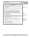
• Use the template provided or the enclosure itself to locate and drill holes for
#8 or M4 mounting screws.
See: Figure 3 -
Installation.
• Secure the enclosure to the wall.
• Bring cable into the enclosure through the conduit entrance and attach
individual wires from the exchange (Tip/Ring/Ground) to the terminal block
(Tip & Ring are not polarity sensitive). If a conduit hub is used, ensure it is
grounded to the ground stud.
See: Figure 4 - Wiring
Connections
• To change the Tone/Pulse setting to pulse, if required:
o Move the jumper from pins 1 & 2 of the Tone/Pulse connector to
pins 2 & 3.
o To change the setting back to tone move the jumper back to pins
1 & 2.
• Reconnect the faceplate harness.
See: Figure 4 - Wiring
Connections
Tip: The SP70A is
factory preset for DTMF
tone.
• Ensure all connections are tight, then replace and secure the cover.
• Connect the telephone into the system.
• Test the unit by making calls to and from another unit on the exchange.