


NUMERIC KEYS
1-9, 0, *, #
On system radio, the twelve button keypad permits
transmission of DTMF digits.
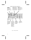
DISPLAY INDICATORS
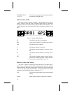
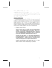
The radio’s display is shown in Figure 3. The character line is used to
display system or area and group or channel names and also operational
messages to the user. The line contains eight Dot Matrix LED characters. The
7 status indicators are used to show the various operating conditions of the
radio.
TX On indicates the radio is transmitting.
BSY Lights when a channel is busy (RF carrier present).
SCN ON indicates scan is enabled.
S ON indicates channel in scan list.
P1 ON indicates selected channel is a priority 1 chan-
nel.
P2 ON indicates selected channel is a priority 2 chan-
nel.
PVT ON indicates selected channel has been pre-pro-
grammed for AEGIS operation. Flashes indicates
receiving an encrypted digital voice call.
DISPLAY ALPHA INDICATORS
The radio is capable of displaying status indicators in the alpha display.
Some of these messages will use the entire display while others use only two
or three characters. When the short message is displayed, it may be on the right
or left of the display (PC programmable). It is separated from the normal
information with an indicator such as an asterisk ("*").
T99 T99 call received alternates with current channel
display.
T99 On Menu display indicating T99 option is enabled.
Figure 3 - Sample MDX Display
12