


Operation (Cont.)
9
6. DELTA-TUNE. For normal operation, set this control to the center posi-
tion. This feature has several uses and can greatly enhance receiver oper-
ation. If a received signal is slightly off frequency, the Delta-Tune control
can be used to Òfine-tuneÓ your receiver. Fine tuning is accomplished by
listening for a more readable signal at the speaker or by noting the S-
meter reading when the Delta-Tune control is operated.
Another use of this control is eliminating adjacent interference. If an
exceptionally high level signal from an adjacent channel is creating inter-
ference on the channel being used, the Delta-Tune can be used to mini-
mize or eliminate the interference. Rotate the control until you obtain
minimum adjacent channel interference. NOTE: Delta-Tune is operable
only in the receive mode.
7. WEATHER CHANNEL SELECTOR. This switch selects any one of the
seven U.S. NOAA Weatherband broadcast stations (see p. 1). Always keep
set to local NOAA Frequency. See enclosed brochure and card for NOAA
travel information. NOTE: The Weather Alert Tone can be turned off by
positioning this selector in the off location.
8. SWR CAL. Used to calibrate the meter for SWR (standing wave ratio)
measurements. Simply switch to "CAL," press the PTT switch on the
microphone and calibrate the meter.
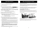
9. CHANNEL SELECTOR SWITCH. This switch selects any one of forty
Citizens Band channels desired. The selected channel is indicated by the
LED readout (17), directly above the channel selector knob.
10. S/RF/SWR/CAL SWITCH. When in the S/RF position, the meter swings
proportionally to the strength of the received signal. When transmitting,
the meter indicates relative RF output power.
When in the "CAL" position, the SWR meter can be calibrated by adjust-
ing the "SWR CAL" control to the "CAL" mark on the meter face.
When in the "SWR" position, the standing wave ratio is measured.
11. NB-ANL/ANL/ OFF SWITCH: When this switch is in the ANL position,
only the automatic noise limiter in the audio circuits is activated. When it
is in the NB/ANL position, the RF noise blanker also is activated. The RF
noise blanker is very effective for repetitive impulse noise, such as igni-
tion interference.
12. PA/CB SWITCH: .Selects the mode of operation. In the CB position, the
PA function is disabled and the unit will transmit and receive on the
selected frequency. The PA function should not be used unless a PA speaker is
connected. In the PA mode, incoming CB transmissions will be heard
through the PA speaker. This allows you to monitor messages when you
are not inside your vehicle.
13. CB/WX SWITCH. Used for selection between receiving Weatherband
broadcasts or normal CB operation. The radio will not transmit in the
Weatherband mode.
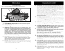
Controls and Indicators
Refer to controls, indicators and connectors as illustrated below:
A. Front Panel
1. MICROPHONE CONNECTOR. Front panel microphone connector.
2. OFF/ON/VOLUME. Turn clockwise to turn power on and set the
desired listening volume.
3. SQUELCH. This control is used to cut off or eliminate receiver back-
ground noise in the absence of an incoming signal. For maximum receiv-
er sensitivity it is desired that the control be adjusted only to the point
where the receiver background noise or ambient background noise is
eliminated. Adjust until the receiver noise disappears. This will require
the incoming signal to be slightly stronger than the average receiver
noise. Further clockwise rotation will increase the threshold level which
a signal must overcome in order to be heard. Only strong signals will be
heard at a maximum clockwise setting.
4. DYNAMIKE. Adjusts the microphone gain in the transmit and PA
modes. This controls the gain to the extent that full talk power is avail-
able several inches away from the microphone. In the Public Address
(PA) mode, the control functions as the volume control.
5. RF GAIN. Adjust as required to optimize signal. This control is used pri-
marily to optimize reception in strong signal areas. Gain is reduced by
counterclockwise rotation of the control.
Operation
8
11
12
14
18
19
16
17
15
13
1 2
3
4
5
6
8
9
10
7