


11
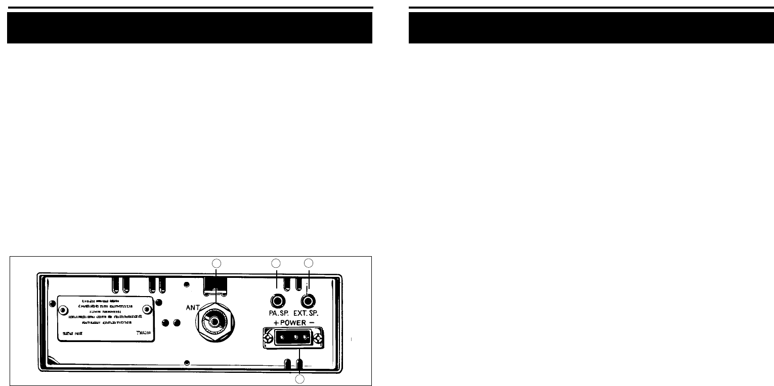
3. ANTENNA CONNECTOR: This SO-239 connector permits connection
of the transmission line cable PL-259 connector to the transceiver.
4.
POWER. This jack permits connection of the DC power to the transceiver.
A power cord with polarized plug is supplied with the radio. The polar-
ized plug ensures that the power will always be connected properly.
Operating Procedure to Receive
1. Be sure that the power cord, antenna and microphone are connected to the
proper connectors before proceeding further. The PA/CB should be in the
CB position.
2. Turn the radio ON by rotating the VOLUME CONTROL clockwise.
3. Set the RF GAIN CONTROL fully clockwise.
4. Set DELTA-TUNE CONTROL to center(click-stop) position.
5.
Rotate SQUELCH CONTROL counterclockwise until incoming signal is heard.
6. Set the CHANNEL SELECTOR Switch to the desired channel.
7. Set VOLUME CONTROL to a comfortable listening level.
8. Engage the SoundTracker system by depressing the button labeled ST.
Listen to the background noise from the speaker. Turn the SQUELCH CON-
TROL slowly clockwise until the noise JUST disappears (no signal should be
present). Leave the control at this setting. The squelch is now properly adjust-
ed. The receiver will remain quiet until a signal is actually received. Do not
advance the control too far, or some of the weaker signals will not be heard.
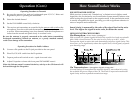
The revolutionary SoundTracker system allows you to reduce unwanted
background noise (static) and increase the signal for better reception.
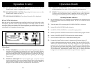
1
2
3
4
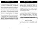
13. SOUNDTRACKER™ INDICATOR. A red LED will illuminate when the
SoundTracker system is engaged on your CB.
14. SOUNDTRACKER™ SWITCH. Depressing this button turns on the
SoundTracker system in your CB.
15. LED CHANNEL DISPLAY. The selected channel will be displayed.
B. Press-To-Talk Microphone
Both the receiver and transmitter are controlled by the Press-to-Talk switch on the
microphone. Press the switch and the transmitter is activated; release the switch
to receive. When transmitting, hold the microphone two inches from the mouth
and speak clearly in a normal voice. The microphone provided with your radio is
a detachable low-impedance dynamic type.
Operation (Cont.) Operation (Cont.)
10
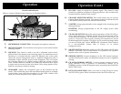
C. Rear Panel
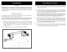
1. PUBLIC ADDRESS: An external 8-ohm 4.0 watt PA speaker may be con-
nected to the PA Speaker Jack when this unit is used as a public address
system. The speaker should be directed away from the microphone to
prevent acoustic feed-back. Physical separation or isolation of the micro-
phone and speaker must be employed when operating the PA at high
output levels.
2. EXTERNAL SPEAKER: The External Speaker Jack is used for remote
receiver monitoring. The external speaker should have 8-ohm impedance
and be rated to handle at least 4.0 watts. When the external speaker is
plugged in, the internal speaker is automatically disconnected.