


Operation (Cont.)
9
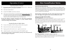
5. RF GAIN. Adjust as required to optimize signal. This control is used
primarily to optimize reception in strong signal areas. Gain is reduced by
counterclockwise rotation of the control.
6. CHANNEL SELECTOR SWITCH. This switch selects any one of forty
Citizens Band channels desired. The selected channel is indicated by the
LED readout, directly above the channel selector knob.
7. S-METER. Swings proportionally to the strength of the incoming signal
during receiving.
RF-METER. Swings proportionally to the RF output power while
transmitting.
8. CB-ANL/PA SWITCH: Selects the mode of operation. In the CB-ANL po-
sition, the PA function is disabled and the unit will transmit and receive
on the selected frequency. The PA function should not be used unless a PA
speaker is connected. In the PA mode, incoming CB transmissions will be
heard through the PA speaker. This allows you to monitor messages when
you are not inside your vehicle. NOTE: ANL (Automatic Noise Limiter)
is a non-switchable feature that is always on to reduce
background noise.
9. NB-OFF SWITCH: When this switch is in the NB position, the RF noise
blanker is activated. The RF noise blanker is very effective for repetitive
impulse noise, such as ignition interference.
10. BRT/DIM SWITCH: Controls brightness of the LED channel indicator
and the multi-function meter, for optimum intensity for day or nighttime
driving.
11. CH.19/CH.9/NORMAL SWITCH. Used for instant selection of emer-
gency Channel 9 (CH. 9 position) or information Channel 19. In
NORMAL position, all 40 CB channels can be accessed by the CHANNEL
SELECTOR switch.
12. RX/TX LED INDICATOR. When your radio is in the CB receive mode,
the LED will be green. When in transmit mode, the LED will be red.
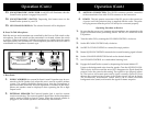
Controls and Indicators
Refer to controls, indicators and connectors as illustrated below:
A. Front Panel
1. MICROPHONE CONNECTOR. Front panel microphone connector.
2. OFF/ON/VOLUME. Turn clockwise to turn power on and set the desired
listening volume.
3. SQUELCH. This control is used to cut off or eliminate receiver
back-
ground noise in the absence of an incoming signal. For maximum receiver
sensitivity it is desired that the control be adjusted only to the point
where the receiver background noise or ambient background noise is
eliminated. Adjust until the receiver noise disappears. This will require
the incoming signal to be slightly stronger than the average receiver
noise. Further clockwise rotation will increase the threshold level which
a signal must overcome in order to be heard. Only strong signals will be
heard at a maximum clockwise setting.
4. DYNAMIKE. Adjusts the microphone gain in the transmit and PA
modes. This controls the gain to the extent that full talk power is available
several inches away from the microphone. In the Public Address (PA)
mode, the control functions as the volume control.
Operation
8
10
11
7
14
15
13
12
1 2
3
4
5
6
8
9