


11
Nothing comes close to a Cobra
®
Controls
10
English
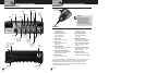
Controls
Controls
•
--
RF Power Hi / Low
Places the transmitter in high power (15 watts) mode when the switch is in
the
hi position and in low power (4 watts) mode when it is in the low position.
--
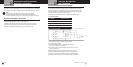
S/RF / SWR / CAL
When this switch is in the S/RF position, the display meter swings proportionally
to the strength of the signal received or the output power being transmitted.
When it is in the
SWR position, the standing wave ratio is measured on the display meter.
When it is in the
CAL position, the SWR function can be calibrated on the display
meter by adjusting the SWR CAL control to move the needle to the calibration mark
on the display meter face.
--
Dim
Adjusts the NightWatch™ panel and meter brightness from min. to max.
The antenna warning LED is not affected by this control.
--
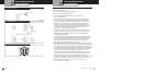
SWR CAL
This control is used in conjunction with the S/RF / SWR / CAL switch to calibrate the
standing wave ratio circuit to full scale on the display meter in preparation for measuring
the standing wave ratio that the antenna is presenting to the transceiver.
The standing wave ratio can be checked to insure that maximum power is being radiated
for the longest signal range. The antenna must be in good condition, properly adjusted
and matched to your transceiver. The SWR function of the display meter lets you easily
measure your antenna condition. To operate this function, select a frequency near the
middle of the range such as 28.850 MHz or the one you plan to use most. With the power
on, set the S/RF / SWR / CAL switch to the
CAL position. Press and hold the microphone
Press-To-Talk button and, using the SWR CAL knob, adjust the meter to the
CAL position
indicated on the display meter. Then, while releasing the microphone button, switch the
S/RF / SWR / CAL switch to the
SWR position. Again press and hold the microphone
Press-To-Talk button and read the SWR indicated. Lower figures are the better, with 1
being ideal. Generally, readings up to 3 are acceptable, but a reading greater than 3
indicates that you are losing radiated power and antenna adjustment may be advisable.
Controls
•
--
NB/ANL / ANL / Off
When this switch is in the ANL position, only the automatic noise limiter in the audio
circuits is activated. When the switch is placed in the
NB/ANL position, the RF noise
blanker also is activated. The RF noise blanker is very effective for repetitive impulse
noise such as ignition interference. When the switch is in the
off position, both the
noise blanker and the automatic noise limiter are disabled.
--
Echo
This control is used to adjust the output level of the echo circuit. It is also detented
at the fully counter clockwise position to turn off the echo circuit.
--
Talk Back
This control is used to adjust the desired amount of modulation talk back that is
present at the speaker during transmit.
Your Mobile Radio Your Mobile Radio