


M1
M2
M3
M4
M5
M6
M7
M8
M9
M10
DIALOGUE
RC
VOL
PROG SCAN
MUTE
POWER
FLASH/PAUSE
REDIAL
ON/OFF
HEADSET
MIC
TM
PHONE
LINE
OFF LO HI
RINGER
AC
ADAPTER
AIR SWITCH
123
6
5
4
78
0
*
9
#
A
B
C
D
E
F
M
N
O
J
K
L
G
H
I
P
R
S
T
U
V
O
P
R
W
X
Y
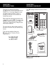
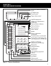
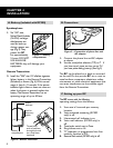
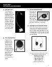
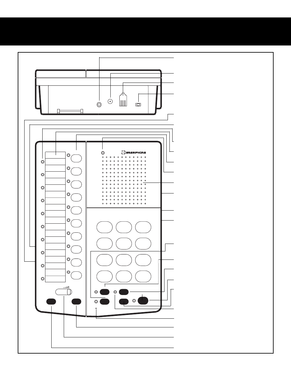
CHAPTER 3
FEATURES IDENTIFICATION
Figure 2 – Features Identification
Jack for Air Switch or accessory
switch
AC adapter plug
Phone line jack
Ringer volume control
Lapel Microphone jack
Headset port (Operational in
RC200 only)
Memory location indicators
Memory directory
Memory buttons
Power indicator
Speaker
Battery compartment
(underneath)
Tone/pulse selector (underneath)
Remote Flash on/off switch, under-
neath (Operational in RC200 only,)
Headset on/off button
(Operational in RC200 only)
Mute button
Flash/Pause button
On/Off button
Redial button
Voice Mail/Unanswered Call
Indicator
Microphone
Scan button
Volume control
Memory Program button
3