


10 Cisco SPA100 Series Analog Telephone Adapters
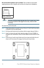
Recommended hardware (not included): Two number-six pan-head
tapping screws, 5/8-in. length, with anchors for sheet rock installation.
WARNING Insecure mounting might damage the ATA or cause injury. Cisco
is not responsible for damages incurred by insecure wall-
mounting.
To mount the unit to the wall:
STEP 1 Determine where you want to mount the unit. Verify that the surface
is smooth, flat, dry, and sturdy.
STEP 2 Drill two pilot holes into the surface 58 mm apart (about 2.28 in.).
STEP 3 Insert a screw into each hole, leaving a gap of 5 mm (0.1968 in.)
between the underside of each screw head and the surface of the
wall.
STEP 4 Place the unit wall-mount slots over the screws and slide the unit
down until the screws fit snugly into the wall-mount slots.
5/8 in. (15.8 mm)