


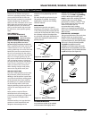
3. Inspect the condition of the gun tip
and nozzle. Remove any weld slag.
Replace gun tip or nozzle if damaged.
Do not operate this
welding machine
with cracked or missing insulation on
welding cables, wire feed gun or power
cord.
1. Replace any unreadable safety labels
on the welder.
2. Use compressed air to blow all dust
and lint from ventilation openings.
3. Clean wire groove on drive roll.
Remove wire from feed mechanism,
remove screws from drive roll
housing. Use a small wire brush to
clean drive roll. Replace if worn or
damaged
The following parts require routine
maintenance:
• Wire feed drive roller
• Gun liner - replace if worn
• Nozzle/contact tips
• Wire - This welder will accept either 4”
or 8” diameter spools. Flux-cored welding
wire is susceptible to moisture and
oxidizes over time, so it is important to
select a spool size that will be used within
!
WARNING
7
Welding Guidelines
6. Rotate Wire Speed Control to setting
number 5 to start then adjust as
needed after test weld.
7. Plug power cord into a proper
voltage receptacle with proper circuit
capacity (See circuit requirements on
front page).
8. Switch welder ON/OFF switch to ON
position.
9. Verify wire is extended 1/4” from
contact tip. If not, squeeze trigger to
feed additional wire, release trigger
and cut wire to proper length.
10. Position wire feed gun near work
piece, lower welding helmet by
nodding head or position the hand
shield, and squeeze gun trigger. Adjust
heat setting and wire speed as needed.
11. When finished welding, turn welder
off and store properly.
Disconnect power
supply and turn
machine off before inspecting or
servicing any components. Keep wire
compartment cover closed at all times
unless wire needs to be changed.
1. Check condition of weld cables and
immediately repair or replace any
cables with damaged insulation.
2. Check condition of power cord and
immediately repair or replace any
cord if damaged.
!
WARNING
Model WG2040, WG2044, WG2045, WG3000
Maintenance
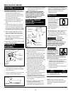
Supply Cable Replacement
1. Verify that welder is OFF and
power cord disconnected.
2. Remove welder cover to expose
the ON/OFF switch.
3. Disconnect the black and white
power cord wires connected to
the ON/OFF switch.
4. Disconnect the green power
cord wire connected to welder
frame.
5. Loosen the cord strain relief
screw(s) and pull cord out of
strain relief.
6. Install new cord in reverse order.
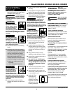
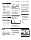
MIG
WT5021
Figure 12 - Nozzle
Operation
(Con't.)
BEFORE EVERY USE:
EVERY 3 MONTHS:
Consumable and Wear Parts
General
This line of welding machines can utilize
the Flux Cored Arc Welding (Gasless)
process or the Gas Metal Arc Welding
(MIG) process. The weld must be
protected (shielded) from contaminates
in the air while it is molten. The gasless
process uses a tubular wire with a flux
material inside. The flux creates a
shielding gas when melted. The MIG
process uses inert gas to shield the weld
while molten.
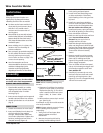
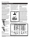
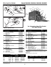
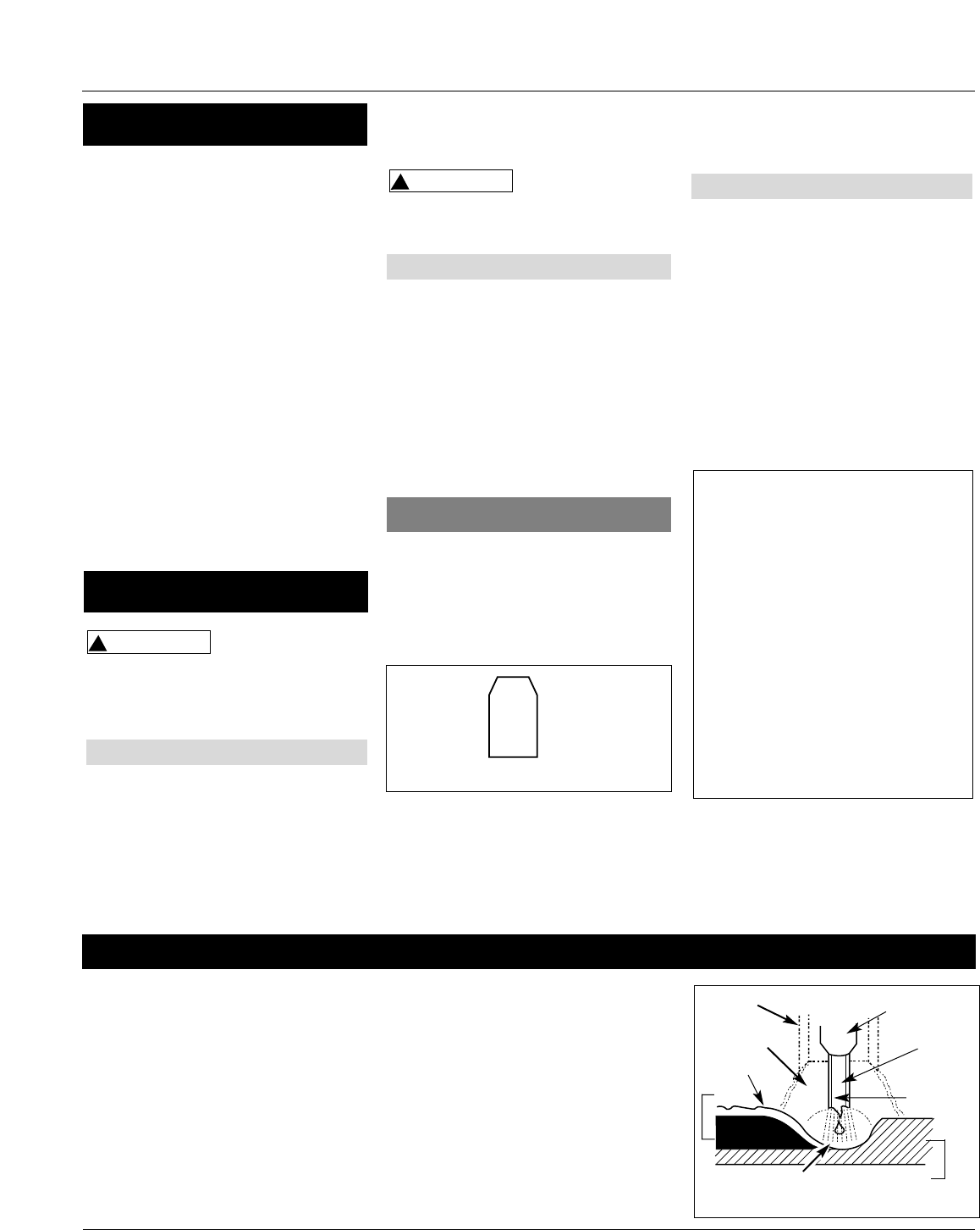
When current is produced by a
transformer (welding machine) and
flows through the circuit to the weld
wire, an arc is formed between the end
of the weld wire and the work piece.
This arc melts the wire and the work
piece. The melted metal of the weld
wire flows into the molten crater and
forms a bond with the work piece as
shown (Figure 13).
Slag
Weld
Wire
Flux
(Gasless
only)
Work Piece
Shielding
Gas
Contact
Tip
Crater
Nozzle
Figure 13 - Weld Components
approximately 6 months. For mild steel
welding, AWS ER70S6 solid wire or AWS
E71T-GS Flux-core wire is recommended.
This welder is setup for .035 (.9mm)
wire. If a different wire size is used, the
wire feed drive roll and contact tip may
need changing. There are two grooves
in the drive roll. The small groove is for
.024 (.6mm) wire and the other is for
.030-.035 (.8-.9mm) wire. Remove the
roller cover and flip the drive roll to
choose the correct groove (See parts
breakdown). The contact tip should
also match the wire diameter used. The
tip diameter is marked on the contact
tip in inches or millimeters.
www.chpower.com
CHANGING WIRE SIZES