


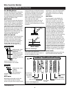
NOTE: Before installing welding wire,
be sure:
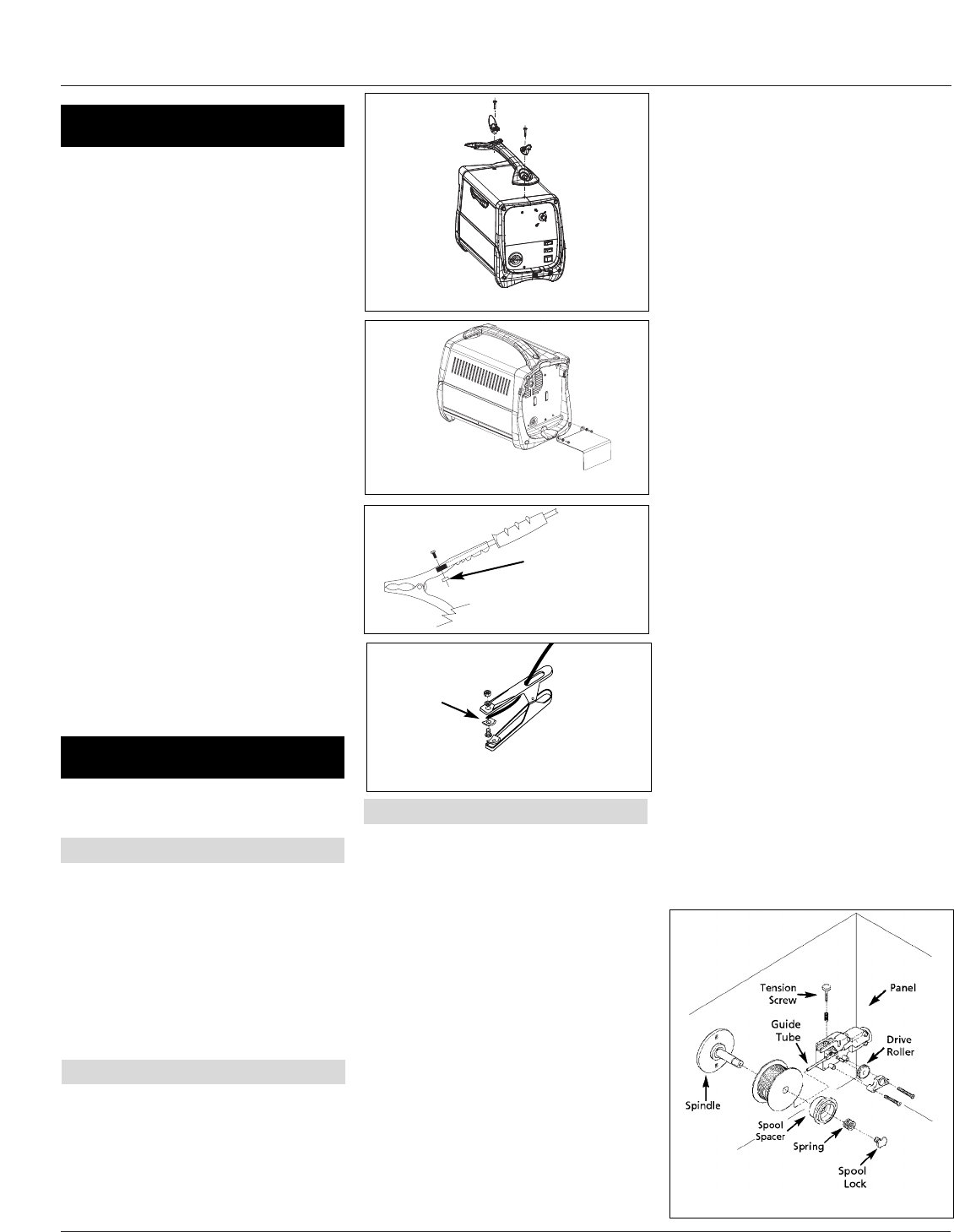
a. Diameter of welding wire matches
groove in drive roller on wire feed
mechanism (See Fig. 5). The drive
roller is marked with metric sizes:
.6mm = .024”, .8 - .9mm = .030 –
.035”
b. Wire matches contact tip in end of
gun. (See Fig. 6).
A mismatch on any item could cause the
wire to slip and bind.
NOTE: Always maintain control of loose
end of welding wire to prevent
unspooling.
1. Verify unit is off and open door
panel to expose wire feed
mechanism.
2. Remove the spool quick lock by
pushing in and rotating 1/4 turn
4
Wire Feed Arc Welder
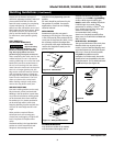
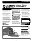
LOCATION
Selecting the proper location can
significantly increase performance,
reliability and life of the arc welder.
● For best results locate welder in a
clean and dry environment. Dust
and dirt in the welder retain
moisture and increase wear of
moving parts.
● Place welder in an area with at least
twelve inches (305 mm) of ventilation
space at both the front and rear of
unit. Keep all obstructions out of this
ventilation space.
● Store welding wire in a clean, dry
location with low humidity to
prevent oxidation.
● Use a properly grounded receptacle
for the welder and ensure welder is
the only load on power supply
circuit. Refer to chart on page 1 for
correct circuit capacity.
● Use of an extension cord is not
recommended for electric arc welding
machines. Voltage drop in the
extension cord may significantly
degrade performance of the welder.
Welding accessories for the welder
are inside wire feed compartment.
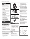
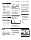
1. Place handle assembly on welder,
aligning two holes in plastic ends
with threaded holes in welder
housing (Fig. 2).
2. Insert screws through cord wraps and
handle ends and fasten into cabinet.
3. Attach cylinder base to unit as shown
(Fig. 3).
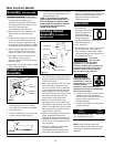
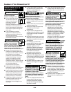
1. Loosen hex bolt/nut on work clamp.
2. Insert cord (labeled ‘work clamp’ on
the front panel of the welder)
through clamp handle. Slide bare
wire under clamp block. Tighten hex
bolt/nut, making sure bare wire is
clamped securely (Figure 4).
counterclockwise. Then remove
knob, spring and spool spacer.
3. Loosen wire feed tensioning screw
on drive mechanism. This allows
initial feeding of wire into gun liner
by hand.
4. Install wire spool onto spindle so
wire can come off spool on the end
closest to the wire feed guide tube.
Do not cut the wire loose yet.
Install spool spacer, spring and quick
lock knob by pushing in and turning
knob 1/4 rotation clockwise.
5. Hold wire and cut the wire end from
spool. Do not allow wire to
unravel. Be sure end of wire is
straight and free of burrs.
6. Feed wire through wire feed guide
tube, over the groove in drive roll and
into gun liner. Snugly tighten wire feed
tensioning screw. Do not over tighten.
Three to four full turns is usually
correct.
7. Remove nozzle by turning counter-
clockwise, then unscrew contact tip
from end of welding torch (See
Figure 6). Plug welder into a proper
power supply receptacle.
8. Turn on welder and set wire speed
rate to 10. Activate gun trigger until
wire feeds out past the torch end.
Turn welder off.
9. Carefully slip contact tip over wire
and screw tip into torch end. Install
nozzle by turning clockwise (See
Figure 6). Cut wire off approximately
1/4 inch from nozzle end.
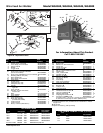
Figure 4a - Work Clamp
Assembly (WG2040,
WG2044, and WG2045)
Figure 3 - Base Assembly
Figure 2 - Handle Assembly
Assembly
Installation
HANDLE AND BASE ASSEMBLY
WORK CLAMP
WIRE INSTALLATION
www.chpower.com
Figure 5 - Weld Wire Routing
Clamping Block
Figure 4b - Work Clamp Assembly
(WG3000)
Clamping Block