


Avaya Inc.
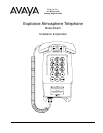
Installation and Operation
Model EA401
Page 8
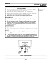
Wiring For Tip & Ring
• After mounting the telephone follow these steps.
• Run tip, ring and ground wires from the local exchange into the lower junction
box. The tip and ring wires must not be connected to the local exchange until
installation is completed. A sealing fitting must be installed within 45.7 cm
(18") on the exchange side of the lower junction box.
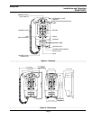
See: Figure 4 - Lower
Junction Box Wiring
• Attach the tip and ring wires to the orange and blue wires from telephone
using twist on wire connectors. Attach #10 ring lugs to the end of the three
green wires and attach these wires to the ground screw in the junction box.
• For tone (DTMF) dialing operation of the telephone, connect the two brown
wires together and protect the connection with a twist-on wire connector. For
pulse dialing operation of the telephone, separate the two brown wires and
insulate the ends to prevent accidental contact with the interior of the junction
box.
• Check the wiring and close the junction box.
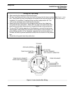
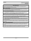
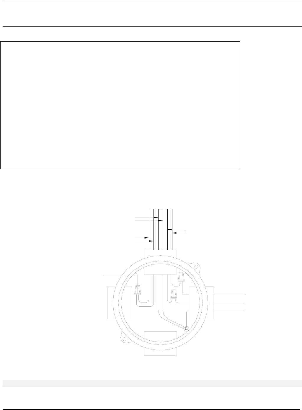
Figure 4 - Lower Junction Box Wiring
FROM EXCHANGE
GROUND
TONE/PULSE: CONNECT
WIRES AND KEEP WIRES
ISOLATED
RING
TIP
(BROWN)
TONE/PULSE SWITCH
GROUND (GREEN)
NOT POLARITY SENSITIVE
(BLUE & ORANGE)
TIP & RING
TO EA401