


User Manual
8 9
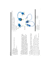
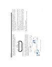
(2) Selection of UTP Cable: For best VGA resolution, please use Cat5
Enhanced cable (350MHz bandwidth), the maximum extended length
of one section (one pair of Transmitter or Receiver) should not exceed
180 meters. The connector must be made by 568B/568B type.
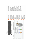
The EIA/TIA defination of 568B in the pin assignment is
(1) orange white, (2) orange, (3) green white, (4) blue,
(5) blue white, (6) green, (7) brown white, and (8) brown
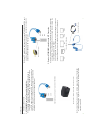
(3) Connect UTP Cable: Plug two ends of UTP cable to Transmitter
and Receiver’s RJ45 SYSTEM LINK ports, the monitor and speaker
connected to Receiver should work now and the LEDs above RJ-45
port should remain ON. You can adjust the FOCUS control of Receiver
to have the best VGA display.
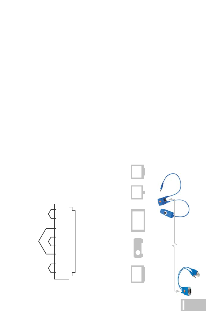
Installation Diagram of Receiver AT-VGA180AR
(4) Function Test: After above installation, you will be able to broadcast the
AV signal to Receiver’s connected monitor and speaker.
(5) Problem and Solving: If you find unstable image or audio problems
after installation, please confirm following list or contact your direct
vendor for further assistance:
a. Check if PC’s VGA resolution and frequency over the limit of monitor
display, if so, please change the VGA configuration from Windows
Control panel.
b. Try to connect Monitor and speaker directly to a PC, and ensure the
basic function of these devices.
c. When using LCD or same type monitor, there might have some image
offset or blinking, please adjust the position, clock or phase of the
LCD monitor, or simply press Auto Adjust / Tune to have a better
image solution.
3. Other Integration and Application:
Please contact your local dealer or distributor for further information.
1 2 3 4 5 6 7 8
JACK POSITION
PAIR 1PAIR 2 PAIR 4
PAIR 3
One-Port
miniTransmitter
One-Port
mini Receiver
Video Monitor & Speaker
Use Cat5e/5e/6
cable up to 180m
Projector PDP LCD CRTTV
VGA
Audio
USB