


User Manual
6 7
/
Installation and Operation
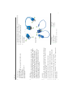
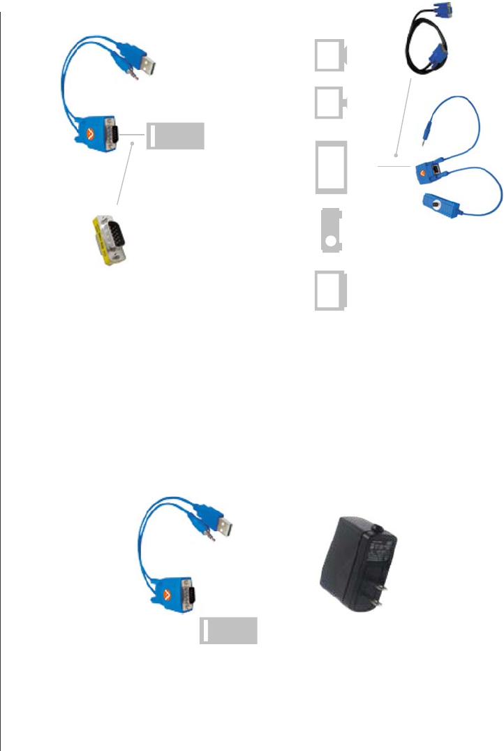
1. AT-VGA180AS Single-Port Transmitter Installation:
)1(
Installation Diagram of System Transmitter AT-VGA180AS
Optional Power Adaptor with a USB 5VDC power output
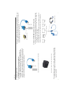
(2) Function Test: Turn on your PC or VGA player, the LED of Transmitter
will blink before VGA signal is turned ON and remain ON after VGA
signal is turned ON.
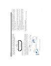
(3) Some PC might have tight space to connect AT-VGA180AS to VGA port,
you may take one short male-female VGA connector to connect in
between AT-VGA180AS and VGA output port.
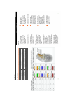
2. Receiver AT-VGA180AR installation and UTP Connection
(1) Power Up: Plug power adapter to the Receiver and connect to monitor
and speaker. The LED above RJ-45 port should blink to indicate the
unconnected status of AV signal.
You can also use a short VGA cable (in the package) to connect in
between Receiver and monitor and place the receiver in other place.
VGA
Audio
USB
Optional VGA Cable
Video Monitor & Speaker
Projector PDP LCD CRTTV
VGA
Audio
USB
M-F VGA Connector
Connecting Transmitter: Take AT-VGA180AS and connect uvw to
computer’s VGA, Audio and USB port. The Transmitter will take
the DC5V power from computer’s USB port and if your computer or
VGA player doesn’t have USB port, please prepare optional power
adaptor with a USB power output to supply the power.