


3
5. PRESET CONTROLS
A) VOX - P9 (Voice activated switch)
This pot adjusts the sensitivity of the VOX threshold of the tel/mic input. Make adjustments as follows:
1) Set the VOX control fully counter clockwise (CCW) (background music should be on).
2) While someone is talking in the page mode, slowly turn the control clockwise (CW) until
the VOX circuit triggers and the background music cuts off.
3) Turn the control an additional 1/8 turn CW and leave at this setting.
If the VOX function has a tendency to drop out, slightly increase (CW) the control setting.
B) Noise - P10 (Talkback background noise balance)
This pot cancels the background noise in the talkback circuit which may be induced into the speaker
wiring by an outside source. (For use with the PD-2 talkback paging adaptor only.)
C) Level - P11
This pot sets the talkback level of the amplifier. (For use with the PD-2 talkback paging adaptor only.)
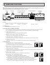
6. GROUND TERMINAL
A chassis ground has been provided to allow separate grounding of the unit, if required.
7. OUTPUT
Connect speaker wires to the terminals labelled OUTPUT. The rated output of all amplifiers is 70V RMS.
Note: To prevent any possible oscillation ensure that the speaker wires are kept away from any input
wiring connected to the terminal strip described below (Item 9).
8. TERMINALS 1-9
In accordance with your particular system installation and requirements, make the following connections
at the terminal block at the right.
A) Terminals 1 & 2 - Tel/Mic (Balanced Input)
Connect to either the telephone system page port, C.O. port, a telephone set or an external microphone
(600Ω balanced - shield to pin 3) to these terminals. Depending on which source is used, dip switches
1 & 2 must be set accordingly.
This voice input can only be activated by the page port dry contacts, the VOX circuit, the C.O. port talk
battery circuit or a strap across pins 5 & 6.
CAUTION: This input must NOT be connected directly to the telephone network.
B) Terminals 3 & 4 - Music/Aux (Unbalanced Input) - (4 - Positive, 3 - Negative)
Connect a music source to these terminals noting that pin 3 is negative. Reversed connection can cause
oscillation. It is important that shielded cable be used to avoid any induced hum. If you are using the
matching PGT-8 tuner, follow the separate instructions included with the tuner. In applications where
this amplifier is used with an external Aiphone paging adaptor, this input may be used as an AUX
input with 10K ohms impedance.
C) Terminals 5 & 6 - Music Mute
When these two terminals are shorted together, the music/aux output of the amplifier will be muted to
allow a tel/mic page to be heard.
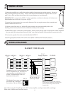
D) Terminal 7 - Page C/2
Connect the appropriate leads from your Aiphone intercom system to this terminal. Refer to the
following wiring diagrams for more details. Set dip switches 7 & 8 according to your system.
E) Terminals 8 & 9 - 12/24 VDC
If an Aiphone intercom system is used in conjunction with this amplifier, connect the matching
power supply for that intercom system to these terminals. Be sure to observe polarity.
24VDC: When using the built-in MC-A adaptor.
12VDC: When using the built-in PD-1/PD-2 adaptor.
2
2
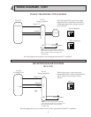
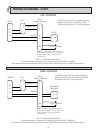
NAMES AND FUNCTIONS - CONT.