


78
ON
2
2
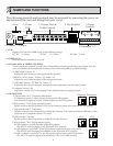
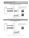
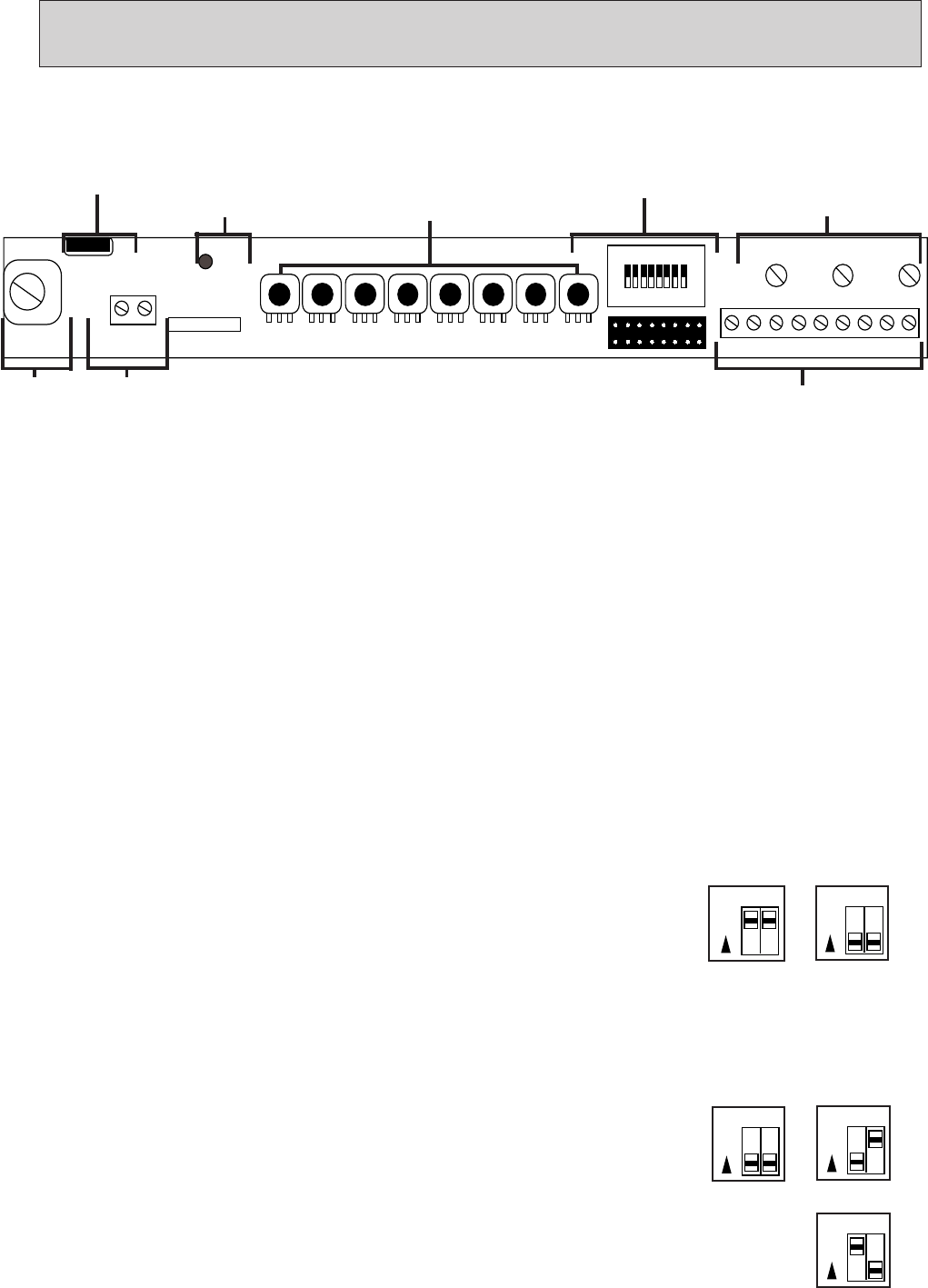
The following controls and terminals may be accessed by removing the screw on
the bottom of the unit and lifting the lower cover.
NAMES AND FUNCTIONS
2
1. FUSE
Replace fuse with 3AG SloBlo's only in the following ratings:
PG-20C 3/4 Amp PG-50C 1-1/4 Amp PG-100C 2 Amp
2. POWER L.E.D.
Indicates that the amplifier is on or off.
3. VOLUME, BASS & TREBLE CONTROLS
These controls are normally set at the time of installation, purposely protruding only slightly from the
cover so that they can be adjusted if necessary, but are less susceptible to accidental change.
A) PRE-TONE Volume - P1
Adjusts the level of the pre-tone signal over the speakers.
B) MUSIC/AUX Volume - P2, Bass - P3, Treble - P4
Adjusts the level, treble and bass of the background music.
C) TEL/MIC Volume - P5, Bass - P6, Treble - P7
Adjusts the level of the telephone/microphone input separately from the music controls.
D) Adaptor Volume - P8
Adjusts the volume level of the paging via the Aiphone intercom/paging system.
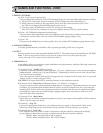
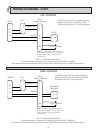
4. DIP SWITCHES
A) Dip switches 1 & 2 - Telephone/Microphone
If a telephone system is used, set both switches to the ON position.
If an external microphone is used, set both switches to the OFF position.
B) Dip switch 3 - VOX (Voice activated switch)
Set this switch to the ON position if VOX music muting is going to be used with tel/mic paging.
C) Dip switches 4 & 5 - Talk battery
Set both switches to the ON position to enable this function. This option provides a talk battery to the
telephone set or telephone system C.O. trunk.
D) Dip switch 6 - Pre-tone
Set this switch to the ON position to enable the Pre-tone function.
E) Dip switches 7 & 8 - Paging adaptor option
For PD-1 adaptor, set both switches to the OFF position.
(The PD-1 is used for paging in the TD-H and TD-Z systems)
For PD-2 adaptor, set switch 7 to the OFF position and switch 8 to the ON position.
(The PD-2 is used for paging and talkback in the TD-H and TD-Z systems)
For MC-A adaptor, set switch 7 to the ON position and switch 8 to the OFF position.
(The MC-A is used for paging with the MC-60/4, RCX, and YKX systems)
P1 P2 P3 P4 P5 P6 P7 P8
TB1
12
LD1
POWER
SW1
21345678
9
VOX
P9
NOISE
P10
LEV
P11
F1
ON
A1002
SER.
GND
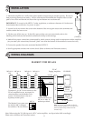
8. Terminals 1 - 9
7. Output
3. Volume, Bass &
Treble Controls
2. Power
LED
1. Fuse
4. Dip Switches
5. Preset
Controls
6. Ground
PD-1
MC-A
Telephone
Microphone
PD-2
12
ON
12
ON
78
ON
78
ON