


TROUBLESHOOTING GUIDE
PROBLEM
1. No call tone or LED when sub calls master.
2. Call tone works, but no communication, or
communication works, but no call tone.
3. Call tone is too loud or too quiet.
4. Master stations cannot call each other.
5. LED lights don't light up when calling master-to-
master.
6. Occupied light is always on.
7. When subs call in, multiple LEDs light up.
8. All Call doesn't work.
9. All call doesn't work, but adaptors are included.
10. When All Call is made, all station LEDs light up.
11. Feedback is heard between intercom stations in
adjacent rooms.
12. System has AC hum when listening to another
station from a master station.
SOLUTION
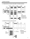
1. Make sure jumper is installed between E & -
terminals at the master and all sub stations (in 2-wire
configuration).
2. Same as #1 in 2-wire system. In 3 wire system, 1 &
E are for communication, and 1 & - are for call-in. Check
continuity and connection of wires.
3. Call tone volume control is located on main PC board
under select switch panel (white 3-pos. switch). Level is
set to maximum. Move to mid or low position.
4. The "C" terminal on the master station means
"CALL", and provides master-to-master communication.
Make sure the "C" of one master is connected to a
designated station # on another master.
5. Station LEDs only light when a sub station calls.
Responding master answers hands free, therefore not
having to select a station.
6. Make sure all black OFF buttons on master(s) are off
(pressed down). Check "R" wire for short to ground. If
occupied light remains lit with "R" wire disconnected
from master, internal damage has occured, and the unit
must be sent in for repair.
7. Make sure station number wires aren't shorted
together. Remove all jumpers between E & - in multi-
master or 3-wire system. Test master by taking wires off
# terminals, then momentarily shorting # terminal to -
(neg). If more than one light comes on, internal damage
has occured, and the master must be repaired.
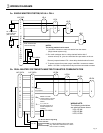
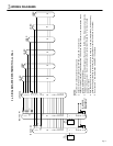
8. All Call is an optional feature requiring a BG-10C and
PS-1225UL for every 10-11 stations in the system.
Make sure adaptors are wired properly. See diagram
#3e.
9. Check connection of P1, P2, P3 terminals between
master and BG-10C's. P1 should read at least 10V DC
when All Call button is pressed. Voice is carried on P2,
P3 wires.
10. If single-call sub stations are used, NP-25V
capacitors must be installed as shown on diagram #3e.
11. Intercom stations should not be mounted back-to-
back on a common wall. Separate them by at least two
feet, or on separate walls if possible. Adjust voice
volume control to eliminate feedback.
12. Intercom wiring must be at least 20" away from any
AC wiring, fluorescent lights dimmer switches, or other
AC devices. Cross at 90 degrees when necessary. If
shielded wire was used, tie all shields together and
ground at one end to an earth ground. If noise persists,
isolate source of noise and separate the intercom station
and wiring from the source.
Pg. 7