


Individual Components for System:
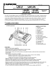
LAF-20C 20-call console-style master station
LAF-20CA 20-call console-style master station with handset
LAF-40C 40-call console-style master station
LAF-40CA 40-call console-style master station with handset
LA-20AS 20-call Add-on Selector
LA-40AS 40-call Add-on Selector
PS-1225UL 12V DC, 2.5A Power Supply. One per system, or
one per BG-10C when All Call/Music is included
(also powers intercom system)
LE-series Any sub station with "LE-" prefix
LS-NVP/B Vandal proof sub station for LAF-C/CA system
SBX-NVP Surface mount box for LS-NVP
SA-1 Surge Arrestor (1 per 2 wires being protected)
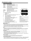
LAF-C TERMINAL DEFINITIONS:
+ Positive 12V DC
- Negative
1~40 Station number, establishes communication to other master or sub
C "CALL", for receiving a call from another master
E Common communication
R Control for Occupied light
("R" is grounded when system is occupied)
Y All Call override control of station in use during All Call
(9V DC when system is in All Call mode)
P1 All Call activation control
(10V DC when All Call is activated)
P2, P3 Audio output for All Call initiation
(Voice transmit from master initiating All Call)
X1~X8 Connection for add-on selector (Type E)
Remove X2/X3 jumper when add-on selector is used.
WIRING & INSTALLATION:
Before Installation:
· Make sure you have the proper power supply(ies) and all necessary and compatible equipment for the system.
· All Call and/or background music are optional features which require additional equipment. See notes below.
· Lay out your system in advance, assigning station numbers for all sub station locations.
· Surge protection for the intercom equipment is strongly recommended. Add SA-1 surge arrestors for the power
supply, plus one per two wires connected to the master station. See diagram on page 3.
Wire:
· Shielded wire is recommended. Use the proper gauge for the distance being run.
· Wiring between masters must be a multi-conductor cable. If more than one cable is used to connect masters,
the "E", "C", and number terminal wires must be in the same jacketed cable. If necessary, run multiple "E"
wires, one in each cable.
Wiring Method:
· Run intercom cables at least 20" away from all AC wiring, fluorescent lights, dimmer switches, and other
electrical or electronic devices. Wiring can cross AC wires at 90 degrees.
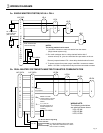
· Sub stations may be homerun to the nearest master station, or daisy-chained. If daisy-chained, include 2
common wires plus one individual wire per station on the run.
· In a SINGLE MASTER SYSTEM ONLY: Subs can be wired with 2 conductors homerun. Jumpers between "E"
and "-" must be attached on all subs and at the master.
Intercom Locations:
· Do not install intercoms near dimmer or light switches, or other electrical wall devices.
· To prevent feedback, do not place sub stations back-to-back on a common wall.
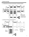
All Call and Background Music:
· The BG-10C adaptor and PS-1225UL power supply are required for each group of 11 stations to receive All Call
and music. This equipment should be installed in an equipment room or in a cabinet. Capacitors (NP-25V) are
required for each sub station on the system. See wiring diagram on page 5 for installation information.
Pg. 2
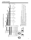
COMPONENTS & WIRING
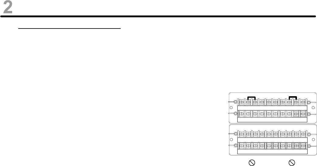
X4X3X2X1EEEE-+
X8X7X6X5P3P2P1YRC
12345678910
11121314151617181920
LAF-20C/CA terminal block
JUMPERS:
In multi-master system, remove E/- jumper at master and
sub stations.
When add-on selector is included, remove X2/X3 jumper.
INTERNAL CONTROLS:
VOX. SENSITIVITY: Potentiometer is located inside unit
behind handset. Adjust for sensitivity of VOX circuit.
CALL TONE WHILE MONITORING:
On the main PC board, there is a jumper labeled W1.
With this in place, the incoming call tone will be muted if
any master in the system is in the Occupied mode. If call
tone is desired while Occupied, cut W1 jumper.
TRANSMIT RECEIVE