


Chapter 3. Operation
3-2 TSU 600 User Manual 61202076L1-1
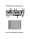
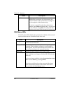
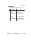
CSU Status LEDs
The CSU status LEDs display the operational condition of the network
interface located on the controller board in the unit.
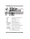
Shift To enter special function keys, press and release
Shift before pressing the key representing the
desired character. See Operation Keys on page 3-5
for a description of the function keys.
To activate a special function key rather than a
number, press Shift and then the key. If you press
the key without using Shift, the numbered item
becomes active instead of the special function key.
Name Description
OK (green) Indicates the operation is in the normal mode and no
errors have been detected.
Test (yellow) Indicates that the network interfaces are operating in a
test mode. This includes a self-test or a test loopback.
When lighted, this LED also indicates that normal data
flow is not occurring on the network interface.
Error (red) Indicates an error such as a BPV, OOF, or CRC.
Alarm (red) Indicates an alarm condition has been detected. When the
alarm condition is no longer valid, the OK LED activates
(turns on).
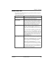
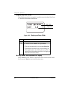
To view an alarm condition, select the
active alarm menu
item or select Alarm by pressing Shift 8.
If the alarm conditions have been corrected, the alarm
which caused the activation of the Alarm LED can be
viewed under the
Unit History menu.
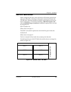
Name Description