


Technician Troubleshooting Guide Model 481BA (D-20)
2
3
Intracom D-20
VOLUME
OFF ON
SP-205A
98
76
5
4
1
2
3
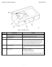
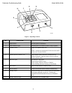
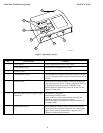
Figure 1. Operating Controls
Key Control Name Function
1 Power Switch Provides power to mainstation.
2 Power Indicator Light Indicates power is on and the system is ready to operate.
3 Volume Control Adjusts INCOMING audio level.
NOTE: Volume level adjustments for alert tone and outside
speakers are set by the installer.
4 Channel Selector Switches (1-6) These switches control talk/listen communication for
numbered channels. Operator touches switch to talk and
releases switch to listen.
5 Indicator Lights Red indicates TALK mode.
Green indicates LISTEN mode.
Yellow (steady) indicates channel on "HOLD."
Yellow (flashing) indicates incoming call WAITING.
6 Hold Switch Places selected channel in "HOLD" mode.
7 All Call Switch Controls conversation with all channels simultaneously.
8 Standby Switch Silences incoming audio to eliminate undesired background
noise pickup when unit is not in use. Touching any
CHANNEL SELECTOR SWITCH releases STANDBY
mode.
9 Standby Indicator Light Indicates unit is in STANDBY mode.