8
EEC3 System Manual
Although the control heads are sealed to withstand damage from exposure to
moisture, they are not designed to be submerged.
STEP 1: Mark the location for the Control Head using the template provided
(see pg. 33). Cut the 3-3/8” x 4-7/8” hole.
STEP 2: Place the Control Head assembly into the cutout. The Control Head
clamps, which hold the control head against the console, have a break off
point indicated by a perforation. For consoles 1/4” to 1” thickness, use brack-
et as supplied. For 3/4” to 1-5/8” thickness, break off clamp at 3/4” break off
point.
STEP 3: Install Control Head clamps and tighten wing nuts provided. Make
sure Control Head is firmly mounted to console.
2.4 Station Communication Cable Routing
Review comments made in Pre-Installation Planning, for determining proper routing of cables. Cables are manufactured
in 10’ increments and are available from 10 - 100 feet.
When routing and connecting station communication cables, BE SURE TO DO THE FOLLOWING:
Use a terminating resistor at each end of the bus (see diagram pg. 11).
Align the cables before connecting them to the proper connector on the Control Head and/or Control
Processor.
REMEMBER:
—Connectors are pre-terminated at the factory and should NEVER be forced into their proper recepticle.
—Make sure that the connector is properly aligned prior to insertion into the recepticle.
—If the connector is properly aligned, only a small amount of force will be necessary to insert the connector into the Control
Processor or Control Head.
—Failure to properly align connector may damage the pins and cause the system to fail.
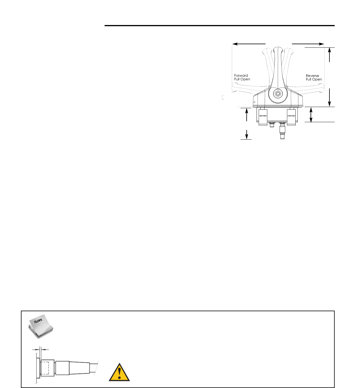
2.5 Connecting the Throttle and Transmission Harnesses
Port and Starboard throttle and transmission cables are attached to the EEC3 Control Processor at the appropriately
labelled connector (see below).
10.68”
(271.37mm)
6.91”
(175.50mm)
1.75”
3.75”
It is VERY IMPORTANT that the Station Communication cable nut be connected tightly. The nut
requires 6-7 turns to completely connect it, and there should be no more than a 2mm (1/16 inch) gap
between the nut and the connector — see diagram below.
WARNING: Failure to follow the instructions above will result in
erratic system performance.
— when fully seated, connector is 1/16” away from nut (max)
— Connector requires 6 full turns to be fully engaged