Group Number
Assignment
1 - 24
25 - 48
49 - 72
73 - 96
2
OFF
OFF
ON
ON
RJ21 Female
Connector
(not included)
RJ21 Male
Connector
(not included)
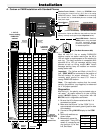
B. Electronic or Digital Phone Installation with LM-2 Message Waiting Lamps
Station/Trunk Switch - Switch to STATION when
connecting the "control line" to a C.O. line or an analog
PABX/KSU station. Switch to TRUNK when connecting the
"control line" to a dedicated phone or unused (loop start)
trunk input.
Neon/LED Switch - Switch to LED when using an LED or
LM-2 on a separate pair.
Green
Red
Reset Button
25T1
25R1
50
25
V/S
S/V
KSU/Digital Phone with LM-2
VIKING©
MODEL MLC-24
VIKING ELECTRONICS, INC. HUDSON, WI 54016
MESSAGE WAITING
LAMP CONTROLLER
RJ21X
FEMALE
RJ21X
MALE
J1
J2
STATION
COM
RESET
TRUNK
NEON
LED
POWER
1 2 3 4
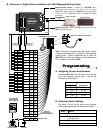
A. Assigning Group Lamp Numbers
Additional MLC-24’s can be added for controlling
up to 96 message waiting lights. Set the dip
switches as shown below.
Dip Switch
1
OFF
ON
OFF
ON
B. Other Dip Switch Settings
Switch
3
3
4
4
ON
OFF
ON
OFF
Feature
When using hard wired LED’s
Use with LM-1’s, LM-2’s or message
waiting phones
Test pattern or diagnostics
Normal operation
Dip switch 3 and 4 can be used to set message
waiting light parameters and operational modes.
13
14
15
16
17
18
19
20
21
22
23
24
Pins
Color
G/BK
BN/BK
S/BK
BL/Y
O/Y
GN/Y
BN/Y
S/Y
BL/V
O/V
GN/V
BN/V
1
2
3
4
5
6
7
8
9
10
11
12
BL/W
O/W
G/W
BN/W
S/W
BL/R
O/R
G/R
BN/R
S/R
BL/BK
O/BK
Pins Color
LED 13
LED 14
LED 15
LED 16
LED 17
LED 18
LED 19
LED 20
LED 21
LED 22
LED 23
LED 24
38
13
39
14
40
15
41
16
42
17
43
18
44
19
45
20
46
21
47
22
48
23
49
24
BK/G
G/BK
BK/BN
BN/BK
BK/S
S/BK
Y/BL
BL/Y
Y/O
O/Y
Y/GN
GN/Y
Y/BN
BN/Y
Y/S
S/Y
V/BL
BL/V
V/O
O/V
V/GN
GN/V
V/BN
BN/V
+
-
+
-
+
-
+
-
+
-
+
-
+
-
+
-
+
-
+
-
+
-
+
-
26
1
27
2
28
3
29
4
30
5
31
6
32
7
33
8
34
9
35
10
36
11
37
12
W/BL
BL/W
W/O
O/W
W/G
G/W
W/BN
BN/W
W/S
S/W
R/BL
BL/R
R/O
O/R
R/G
G/R
R/BN
BN/R
R/S
S/R
BK/BL
BL/BK
BK/O
O/BK
+
-
+
-
+
-
+
-
+
-
+
-
+
-
+
-
+
-
+
-
+
-
+
-
LED 1
LED 2
LED 3
LED 4
LED 5
LED 6
LED 7
LED 8
LED 9
LED 10
LED 11
LED 12
Polarity Pins
Color
Black
Yellow
Control Line
Unused PABX
Trunk Input or
Analog station
Control Phone
Programming
.75”
1.00”
LM-2 (Fax Back Document 660)
1000 foot
maximum run
using 26 AWG wire
Note: Electronic or digital telephones usually require
a separate dedicated pair for operation of the message
waiting lamps. When a dedicated pair is used, the
MLC-24 can provide low voltage for direct operation of
LED indicators, such as the LM-2.
Optional LM-24D
or
Optional LM-12W
(Fax Back Document 665)
(Fax Back Document 670)
or
C.O. Line


