2 947212
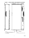
P4
P2
SW1
P3
AC
Power
Fuse
P1
P1
Side View Top View
Power
LED
115/230
Switch
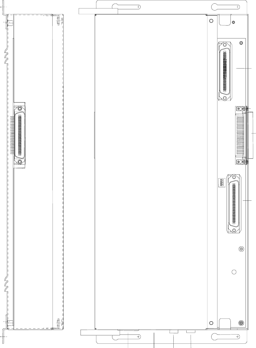
FIGURE 1 - V-2925A CONTROL AND CONNECTOR LOCATIONS
P1
P2
P3
P4
SW1 - BGM Group Select Dip Switch (See Table)
Connectors:
- Connects to the V-2924A Control Unit
- Connects to an additional V-2925A Expansion Unit
- Switch Inputs
- Speaker Outputs
Switches:
Battery Backup
Connector


