


CONTROLS DFUNCTIONS
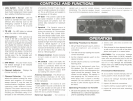
,. ANL Switch - You can select the
Automatic Noise limiter to help re-
duce harsh background noise caused
by a varietyof interferencesources.
2. Instant CH 9 Switch - Use this
switch to override the main channel
selector and instantly tune to the
emergency channel 9. Switch back
to return to normal 40 channel
operation.
3. TX LED - An LED lights to indicate
when the radio is transmitting.
4. Microphone - The operational
mode of the CB is controlled by the
push-to-talk switch on the mic. Press
the switch to activate the transmitter
and disable the receiver. Release the
switch to enable the receiver and dis-
able the transmitter. Wh~n transmit-
ting, hold the micabout 2 inches from
your mouth and speak clearly in a
normal voice. The mic included with
the PRO 520e is a detachable ele-
ctret type.
5. S/RF Meter - This LEDmeter shows
the relative strength of the received
signal or the RF output.
6. Channel Indicator - Displays the
channel currently in use.
7. Channel Selector - This switch
selects the desired channel for trans-
mission and reception. All channels,
except channel 9, may be used for
communications between stations
operating under different license.
Channel 9 has been reserved by the
D.OC. foremergency communications
involving the immediate safety of in-
dividuals or the immediate protection
of property. Channel 9 also may be
used to render assistance to a motor-
ist. This is aD.O.C.rule and applies to
all operators of CB radios.
8. RF Gain - This control is used to ad-
just signal reception in areas where
strong signals are present. Turn the
control fully clockwise for maximum
reception.
9. Squelch - The Squelch control is
used to eliminate background noise
during the absence of a transmission.
Turn the control fully counter clock-
wise, then slowly rotate it back, clock-
wise until all noise disappears. At this
setting any transmission must be
slightly stronger than the background
noise to "Break Squelch" or to be
heard. Further clockwise rotation will
increase the threshold at which a sig-
nal will be heard. Youcan select any
level to "Break Squelch".
'0. Volume Control - Rotate clockwise
to turn radio on and to increase
volume.
, ,. PA Switch - Select the PublicAd-
dress mode when an external PA
speaker is connected. When the PA
mode is selected, the CB radio will be
disabled. Adjust the PA output level
by rotating the volume control.
Antenna Connector - Thisfemale con-
nector permits connection of the trans-
mission line cable male connector (PL-259)
to the transceiver.
Public Address - An external 8 ohm
7-watt speaker must be connected to the
"PA SP"jack located on the back of the
unit. The speaker must be directed away
from the mic to prevent feedback.
External Speaker - The external
speaker jack is used for remote receiver
monitoring. The external speaker should
I have an 8 ohm impedance and be rated at
least 7 watts. When.;tn external speaker is
connected, the inre,[nal speaker is
disabled.
OPERATION
,""
Operating Procedure to Receive
I
,. Besure that the power source, antenna
and microphone are properly
I connected.
I 2. Turnthe unit on by rotating the volume
control clockwise.
3. Set the channel selector switch to the
desired channel.
I 4. Set the volume control to a comfortable
listening level.
5. listen to the background noise from
the speaker. Turn the squelch control
clockwise until the noise disappears (no
signal should be present). Leave the
control at this setting. The squelch is
now properly set. The receiver will re-
main quiet until a signal is actually
received. Do not advance the control
too far, or some weaker signals will not
be heard.
: Operating Procedure to D'ansmit
1. Be sure the operator has read and un-
derstands D.O. C. rules and regulations
prior to operating the transmitter.
2. Select the desired channel for
transmission.
3. Ifthe channel isclear, depress the push-
to-talk svlitch on the side of the micro-
phone and speak in a normal voice.
CAUTION: The transceiver Voltage
Standing Wave Ratio (VS.W.R.)measure-
ment must be performed prior to the use
of the transmitter. A "VS.WR." ratio in ex-
cess of 2:' may damage the transmitter.
Please check your SWRreading frequently
by using an SWRmeter.
Preventative Maintenance
At six to twelve month intervals, the fol-
lowing system checks should be made:
,. Check the Voltage Standing Wave
Ratio (VS.WR.)
2. Inspect all electrical connections.
3. Inspect antenna coaxial cable for wear.
4. Inspect all screws and other mounting
hardware.