


www.U-LineService.com 4 02/2005
BI-98 Ice Maker
Your U-Line product has been designed for either free-
standing or built-in installation. When built-in, your unit
does not require additional air space for top, sides or rear.
However, the front grille must NOT be obstructed and
clearance is required for water and electrical connections
in the rear.
Note: Unit can NOT be installed behind a closed cabinet
door.
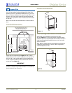
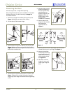
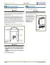
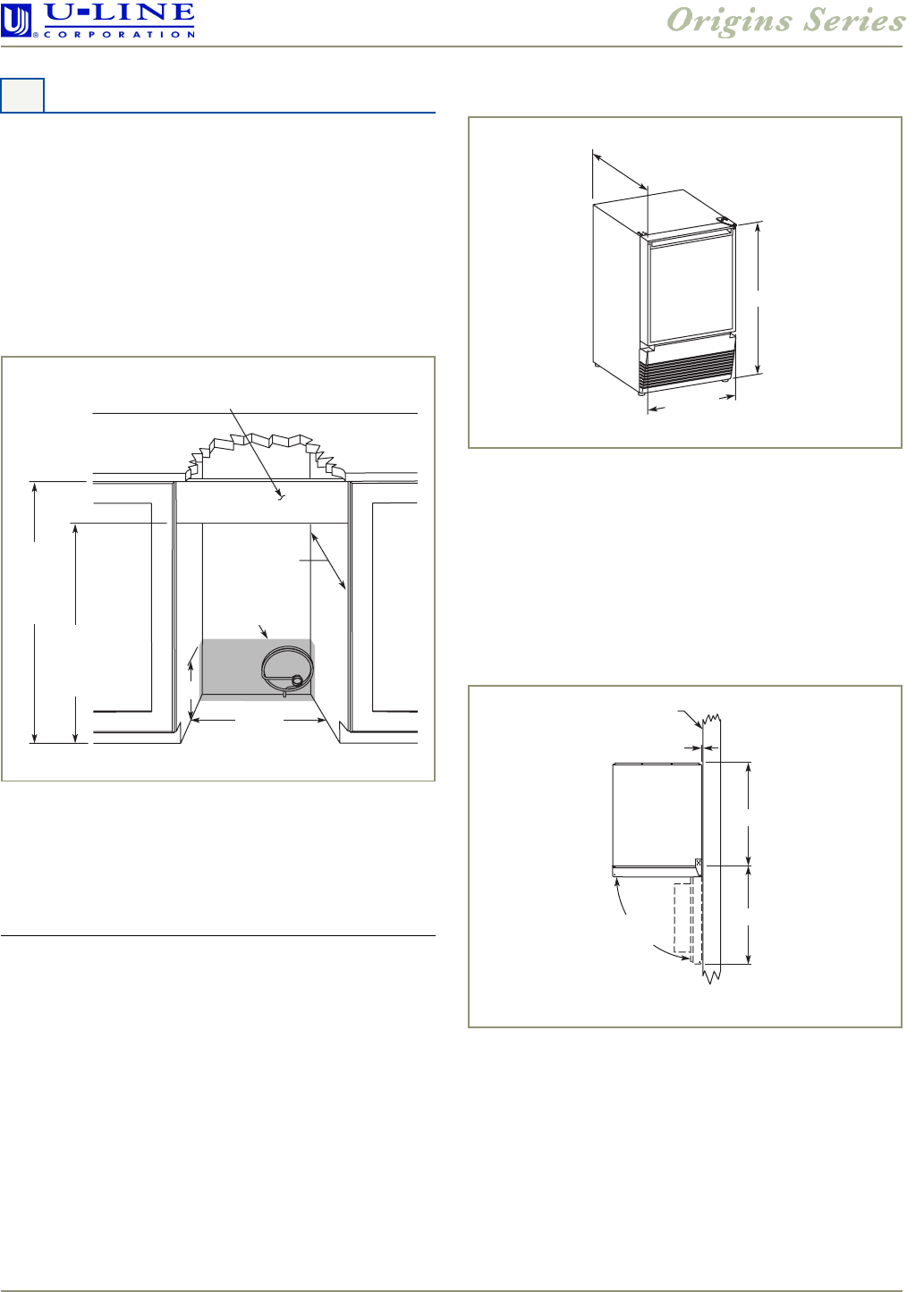
Cut-Out Dimensions
Follow the cut-out drawing in Figure 1. The 15-3/16"
width allows 1/4" for ease in installation and removal of
the unit. 24" is the counter depth in most installations.
21-1/2" depth includes the door, handle and water line
connection (see Figure 2).
IMPORTANT
It is extremely important that the unit sits on a level
surface, as it does not have feet levelers. If it is not level,
the ice mold will not fill evenly.
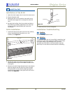
Product Dimensions
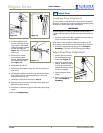
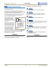
Door Swing/Clearances Information
Units have a zero clearance for the door to open
90° (see Figure 3). U-Line recommends a minimum door
clearance of 1/4" to accommodate the handle if the unit is
right-hand hinged and installed next to a wall or similar
type of structure.
Note: When a raised panel is used, additional clearance is
needed for easy removal of ice bin if door hinge side is
installed adjacent to wall.
3 Prepare Site
8"
Typical
Counter
Height
34-1/4"
to
35-1/8"
Cut-Out
Height
27-1/2"
to
27-5/8"
Filler Panel (Not Provided by U-Line) –
May Be Added Above or Below Unit
to Enclose for a Built-In Look
15-3/16"
21-1/2"
Minimum
See Electrical
Specifications
for Power Supply
Figure 1
20"
Including
Handle
27-3/8"
14-15/16"
Figure 2
1/4" Min.
Wall
90°
Door Swing
17-3/8"
16-1/2"
Figure 3