


5
Installation
Installation
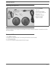
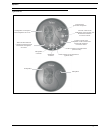
1. Remove the two screws (one on each side) holding the mounting plate to the operator assembly. (See Figure 2 .)
2. Measure and identify the location where the intercom is to be mounted.
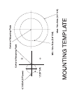
3. Attach the mounting template to the window (customer assembly side) being sure to center the appropriate guide in the
location identified in step 2. Note, there are two guides provided on the last page of these instructions. Use either the single
large hole, or multiple small holes depending on which method you choose. Using the multiple small hole method with
bullet-proof glass will afford maximum operator protection (Figure 4 on page 6).
4. Cut and/or drill the hole(s) from the customer assembly side.
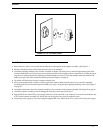
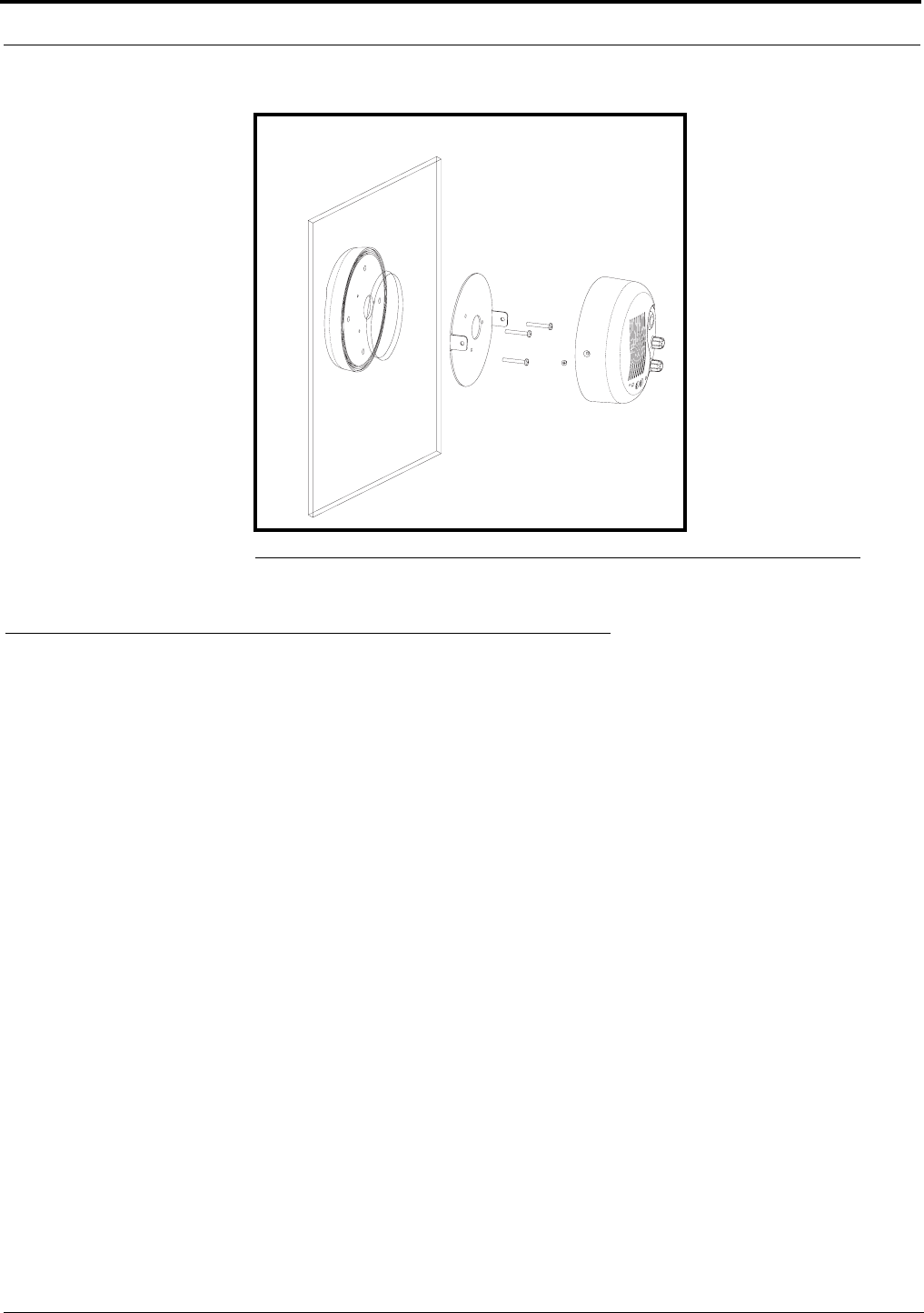
5. Have an assistant place the customer assembly against the window. Make sure the holes line up correctly. Attach the
mounting plate removed from the operator assembly (see step 1) using the three supplied mounting screws. (See Figure 5
on page 6).
6. Attach the cable harness from the customer assembly to the connector on the operator assembly (See Figure 6 on page 6).
7. Attach the operator assembly to the mounting plate using the screws removed in Step 1.
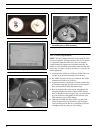
8. Plug the RJ-45 end of the ICW-3 power supply interface cord into the ICW-3. the connector is located on the bottom of the
ICW-3 on the operator assembly side. Secure the cord to the glass using wide clear adhesive tape.
9. Connect the power supply to AC power using the supplied IEC cord. Attach the ICW-3’s power cord to the power supply.
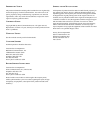
FIGURE 2. ICW-3 Assembly Detail