


TR-24 Control and Connection – Top Panel
1.
Volume Control and Power Switch – Turns the power on/off and controls
headset volume.
2.
Battery / Power Light – Indicates the beltpack has power, either from the internal
battery or AC power connected to the unit.
• GREEN = Beltpack battery OK
• RED = Battery Low ( >15 minutes left)
• NO Light = Battery Depleted
3.
Button One and Light – Selects audio channel one. The channel light has two
modes depending on the <TALK> button’s state.
• Light Solid = Talk and Listen enabled.
• Light Flashing = Listen only enabled (Push-to-TX).
4.
Talk Button – Enables the headset microphone. The button has two modes:
• Momentary = Press and hold for over ½ second
• Latch on/off = Tap button and microphone is enabled, tap again to turn
off.
5.
Button Two and Light – Selects audio channel two. The channel light has two
modes depending on the <TALK> button’s state.
• Light Solid = Talk and Listen enabled.
• Light Flashing = Listen only enabled (Push-to-TX).
6.
Charge / Power Jack – Used to charge the internal battery or power the unit
directly off a wall outlet. Accepts a 5.5mm x 2.5mm plug with the center positive.
Must be supplied with a 12VDC regulated power supply with at least a 400mA
current capacity.
BTR-24 Control and Connection – Front Panel
1.
On/Off Switch– Turns the power on/off to the base station.
2.
Power / Low Battery Light – Indicates the base station has power, either from the
internal battery or AC power connected to the unit.
• GREEN = Battery OK
• RED = Battery Low (>30 minutes left)
• NO Light = Battery Depleted
3.
AP Active Light – This green light flashing indicates that the BTR has
successfully booted and is operating.
4.
RF Channel Display – The display indicates the RF channel for which the unit is
set.
5.
Select Button – Hit the button to select the desired RF channel for the base station.
The button has two other functions as follows:
• Clear Scan – Press and hold the button until the decimal point starts to
flash (about 3 seconds) then release. The unit will scan all the RF
channels, then set the unit on the one with the least WiFi activity.
• Lock – Press and hold the button until the decimal point is on solid (about
10 seconds) then release. The base will be locked on the displayed
channel until rebooted or the decimal point is turned off by the same
procedure.
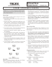
TR-24 Control and Connection – Bottom Panel
7.
Charge Light.
• RED = Beltpack battery is charging.
• GREEN = Beltpack battery is charged.
8.
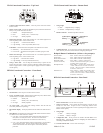
Headset Connector – Standard 4-pin XLR connector.
9.
Configuration Jack – RJ-45 jack used to interface the beltpack to an Ethernet
cable. Jack may be used for wired mode and configuring the beltpack.
Beltpack Button Combinations (All have voice prompts):
Wireless Mode.........Press <TALK> until unit is done booting.
Wired Mode ..........Press <TWO> until unit is done booting.
Master Wireless Mode.....Press <ONE> until unit is done booting.
Momentary Mode .......Press <ONE> +<TALK>+<TWO> for 3
(Push-to-TX full time) seconds. Press the three buttons again to go back to
the default “Push-to-Latch” mode.
Microphone Gain .......Press <ONE> + <TALK> for 3 seconds. Keep
<TALK> held down and use <ONE> to decrease
the gain, <TWO> to increase it. Release all buttons
for at least 1 second to set.
Sidetone Level.........Press <TALK> + <TWO> for 3 seconds. Keep
<TALK> held down and use <ONE> to decrease
the level, <TWO> to increase it. Release all buttons
for at least 1 second to set.
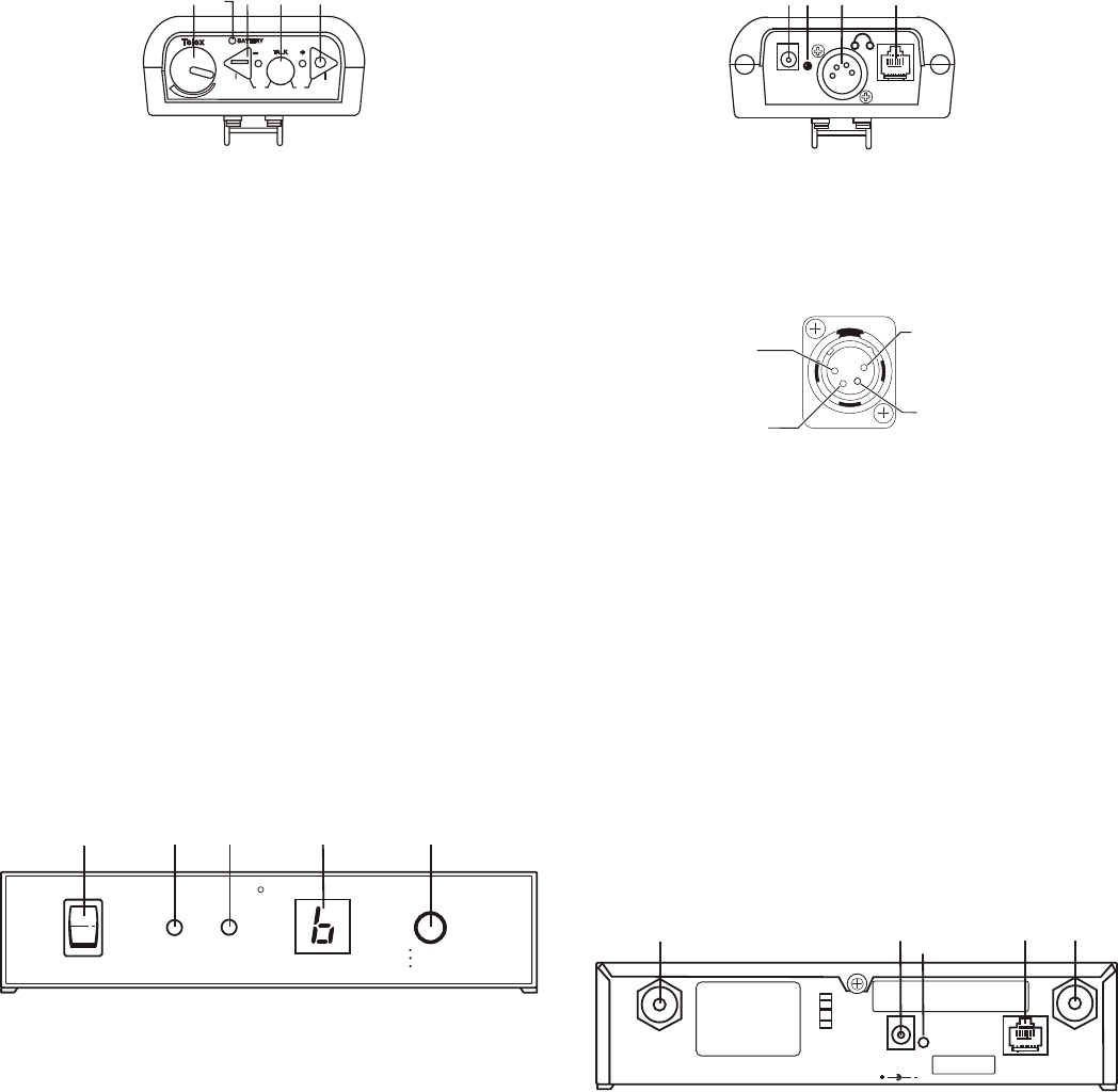
BTR-24 Control and Connection – Rear Panel
6.
Receive Antenna Jack – Reverse TNC receive jack.
7.
Charge / Power Jack – Used to charge the internal battery or power the unit
directly off a wall outlet. Accepts a 5.5mm x 2.5mm plug with the center
positive. Must be supplied with a 12VDC regulated power supply with at least a
400mA current capacity.
8.
Charge Light.
• RED = Battery is charging.
• GREEN = Battery is charged.
9.
Configuration Jack – RJ-45 jack used to interface the base station to an
Ethernet cable. Jack may be used for configuring the base station or
connecting multiple base stations.
10.
Transmit Antenna Jack – Reverse TNC transmit jack.
Made in U.S.A. 02/2007
1
2
3
OFF
MIC
S.T.
AJ
D
1
2
4
5
AJ
D
ONON
OFFOFF
LOW
BATTERY
POWER
AP
ACTIVE
CHANNEL
Telex
R
SELECT
CHANNEL
CLEAR SCAN
LOCK
BTR-24
1
2 3 4 5
CHG
EXT
6
7
8
9
RED: CHARGING
GREEN: READY
PGM
TRANSMIT
ANTENNA
12 VDC
400mA
CORD
RETAINER
RECEIVE
ANTENNA
BTR-24
Telex Communications, Inc.
This device complies with Part 15 of the FCC Rules
Operation is subject to the following two conditions
(2) This device must accept any interference, received.
(1) This device may not cause harmful interference, and
Including interference that may cause undesired
operation.
Made in U.S.A. XXXXXXXXX
FCC ID:B5DM525
IC: 1321A-XOAP
S.N.: 000003
6
7 9
8
10
(1) Microphone
Shield (-)
(2) Microphone
Audio (+)
(3) Headphone
High (+)
(4) Headphone
Low (-)