


2.4 Connecting the Handset
Plug one end of the coil cord into the RJ-10 receptacle on the
handset, and the other end into the receptacle on the left
side of the base. Place the handset into the cradle of the base.
2.5 Connecting the SIP LD Series to the network
WARNING! Risk of electrical shock! Dangerous voltages may
be present on the terminals of the network patch cable after
it is plugged into the network wall jack. Connect the patch
cable to the base first, then to the network wall jack.
2.5.1 SIP LD Series Version 1 (Local Power)
Connect Network to the Inline Power Adapter.
For this version, the network interface is assumed to NOT
be PoE compatible. For installation within North America,
Teledex provides an inline power adapter, which has two
network ports labeled “PHONE” and “LINE” respectively. (For
installation outside North America, please contact Teledex for
information on obtaining an approved inline power adapter.)
Plug one end of a network patch cable into the RJ-45 jack at
the top of the SIP LD series base. Connect the other end of
this cable to the RJ-45 jack labeled “PHONE” on the power
adapter. With a second network patch cable, plug one end
into the RJ-45 jack labeled “LINE” on the power adapter.
Connect the other end of this cable to the network wall jack
designated by the network administrator. Plug the power
adapter into an unswitched electrical outlet.
2.5.2 SIP LD Series Version 2 (PoE)
For this version, the network interface is assumed to be
PoE compatible, and power present at the Ethernet jack.
Plug one end of a network patch cable into the RJ-45 jack
at the top of the SIP LD series base. Connect the other end of
this cable to the network wall jack designated by
the network administrator.
2.5.3 SIP LD Series Version 3 (Dual power)
This version can work in either local power or PoE mode,
according to the different setup of the power jumpers
underneath the phone. When the phone is set to work in
the local power mode, connect to the network through
the inline power adapter as described in subsection 2.5.1.
When the phone is configured to work in PoE mode,
follow the instructions described in subsection 2.5.2.
CAUTION: Do not connect a standard telephone line cord
to the network RJ-45 jack. A standard telephone cord
connector can fit into the RJ-45 jack; however there is a
risk of damaging the equipment if this is done.
NOTE: The SIP LD series will not function until it has been con-
figured and activated by the network administrator.
2.6 Connecting a PC to the SIP LD Series
If the installation environment has only one active network
jack, and another network device such as a PC must share the
same space, that device should be disconnected from the wall
jack and reconnected to the RJ-45 jack on the right side of the
SIP LD series.
CAUTION: The cable from the network wall jack must be
connected to the jack on the top of the phone, and if there is
a PC, it must be connected to the jack on the right side of
the phone. Otherwise the phone will not function.
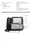
2.7 Arranging the SIP LD Series on the Desk or Table
Route the network cable toward the rear of the base of
the phone, and attach the desk/wall mounting bracket by
inserting the tabs into the matching holes in the base. Place
the phone in a convenient location on the desk. Place the
handset on the cradle and confirm that the hookswitch is
properly depressed by the weight of the handset.
2.8 Mounting the SIP LD Series on a Wall
The SIP LD series can be mounted on a wall or other
vertical or near-vertical surface surface. To do so, the desk/
wall mounting bracket should be rotated 180 degrees,
compared to the desk mounting position. Use screws
(and anchors, if necessary) to match the hole pattern in
the bracket. The wall mounting clip (just underneath the
hookswitch) should be removed and re-installed after
rotating it 180 degrees.
To remove the clip, push it firmly toward the hookswitch.
The clip will hold the handset firmly in the cradle, and
allow it to depress the hookswitch when the phone is
not in use.
3. Configuring the SIP LD Series
Once the SIP LD series has been unpacked, set up on the
desk (or mounted to a wall), and connected to the network,
the network administrator should be notified that the unit
is ready for network configuration and activation. Once this
process has been completed, it will receive power from the
network and begin to function.
3.1 Starting Up
The SIP LD series will automatically begin to function once it
has been connected to the network, configured and activated
by the network administrator. The network will
detect the presence of the SIP LD series and supply power and
data to it (there is no on/off switch). Once
power has been applied, it takes about ninety (90) seconds
for the SIP LD series to be ready for configuration.
3.2 Online Configuation
The SIP LD series supports web-based online
configuration, and can be configured through another
PC. The default IP address for the phone is 10.10.1.254.
The network administrator should configure the SIP
LD series to another static IP address, or activate
the DHCP function through the online configuration.
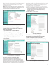
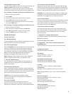
3.2.1 Visit the Configuration Portal (Fig.2)
Use the link http://(IP Address):8080 to access the web portal
of the SIP LD series. The default IP address is 10.10.1.254, so
use the link http://10.10.1.254:8080. The username and pass-
word will be required to access to the web portal.
The default logins are (case sensitive):
Username: Admin
Password: iPhone06
4