


press the “down” arrow key to decrease the volume level, and
press the “up” arrow key to increase it.
ADJUSTING HANDSET RECEIVE VOLUME
The handset has eight (8) volume levels.To adjust the handset
volume, locate the volume up/down keys, located on the
handset, below the “
#” key. Pressing the “minus” (-) key will
decrease the volume level, while pressing the “plus”
(+) key
will increase it.
AUTO DIAL KEYS
The DCT2900 series has either five (5) or ten (10) programmable
guest service (auto dial) keys, depending on the model you own.
These keys can be programmed to automatically dial telephone
numbers, or to activate telephone system features.To program the
auto dial keys (programming can only be done from base unit
):
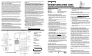
1. With the phone “on hook” (inactive) and the faceplate
removed, press the recessed
STORE key (see diagram).
2. Enter the desired telephone number (up to 15 digits in
length) to be stored.To enter a “pause” in the number
string, press the
REDIAL key as necessary.
3. Press the
STORE key again.
4. Press the auto dial key where the number is to be stored.
Programming is now completed for that auto dial key.
To program additional keys, repeat this process.
RECEIVING A CALL
An audible ring and flickering red LED indicate an incoming call.
T
o answer the call using the handset while it is not on the base:
1. Pick up the handset.
2. Press the line key for the ringing line.The handset will go
“off-hook” answering the ringing line.
3. To end the call, place the handset in the base unit cradle, or
press the lit line key on the handset.
T
o answer the call using the handset while it is resting on the base:
1. Pick up the handset from the base.The phone will
automatically connect to the correct, ringing line.
2. To end the call, replace the handset in the base unit cradle,
or press the lit line key on the handset.
To answer the call using the speakerphone:
1. Press the line key for the ringing line.The speakerphone will
go “off-hook”, answering the ringing line.
2. Or, press the
SPKR key. The phone will automatically select
the correct, ringing line.
3. To end the call, press the
SPKR key again.
PLACING A CALL
Using the handset:
1. Pick up the handset and select either line 1 or line 2. Listen
for dial tone and dial the desired number.
2. After the call is complete, press the key for the selected line
again to end the call.
Using the speakerphone:
1. Press key for either line 1 or line 2, or press SPKR.
2. Listen for dial tone, and dial the desired number, or press an
auto dial key to dial a preprogrammed number.
3. After the call is complete, press the
SPKR key to end call.
REDIAL
The DCT2900 series can automatically redial the last number
dialed. On the handset, press the
REDIAL key to redial the last
number.
CONFERENCE
The CONF key allows for three-way conversations. Depending
on the situation, you may initiate a conference call using one of
these methods:
User initiates two calls:
1. Place call to first party, then place them on hold by
pressing the
HOLD key.
2. Using the second line, place call to second party.
3. Once that party is on the line, press
CONF to join the first
caller with the second party and yourself.
User initiates one call:
1. After receiving a call from first party, place them on hold
as above.
2. Using the second line, place call to second party.
3. Once that party is on the line, press
CONF to join the first
caller with the second party and yourself.
User includes two callers:
1. After receiving a call from first party, place them on hold
as above.
2. After receiving call from second party, press
CONF to join
the first party with the second party and yourself.
To terminate a conference call, pressing a line key will maintain
the connection with that line, while dropping the other line.To
terminate the call entirely, press either the
CONF key or SPKR key
to disconnect both parties.
USING THE HOLD KEY
The HOLD key places the call on hold locally at the cordless
telephone.
T
o place a call on hold:
1. With a call active, press the red HOLD key on either the
handset or base unit.
2. The red line LED will flash, indicating the call is on hold.
3. If a conference call is active, pressing
HOLD will place all
connections on hold.
T
o remove a call from hold:
1. Press the line key of the call on hold.This will remove the
call from hold, making the call active again.
2. The red line LED will return to steady illumination, indicating
the line is active.
3. During a conference call, to remove both lines from hold,
press the
CONF key.
T
o change phones after placing a call on hold:
1. Place the call on hold as above.
2. Pick up the call at another telephone that is on the same
line.The telephone will activate the line and remove the hold
at the original telephone.
TO MUTE THE SPEAKERPHONE
1. Press the MUTE key on the base unit.The red LED above
the
MUTE key will illuminate.The party on the other end
will not be able to hear you when the
MUTE LED is lit.
2. Press the
MUTE key again to turn off the mute feature.
The
MUTE LED will go out.
CONVERTING FROM DESK TO WALL MOUNT
The DCT2900 series can be adapted for wall mounting applica-
tions.The conversion is easiest to make when the handset and
cords are not connected.
1. Located on the handset cradle, above the speaker grill, is the
wall/desk mount clip. Remove this clip by firmly pushing it
upward towards the top of the phone.
2. Flip the clip over (top to bottom) so that the protruding edge is
towards the top of the phone and replace it in its slot.This edge
will hold the handset when the phone is mounted on the wall.
3. Turn the telephone over so the bottom is up, facing you.
Place it on a non-abrasive surface to prevent scratching.
4. Locate and remove the mounting bracket. Firmly push back
and pull up to remove two of the four retaining tabs.
5. Rotate the mounting bracket 180º degrees clockwise
, so that
the mounting eyelet on the bracket is facing in the same
direction as the other mounting eyelet located on the
bottom of the telephone.
6. Insert the top two retaining tabs of the mounting brackets
into the mounting bracket slots (located near the middle of
the telephone).Then firmly push down to insert the retaining
tabs on the opposite side of the mounting bracket.
7. Connect a 15-foot RJ-45 cord into the
LINE jack on the back
of the phone.
8. Turn the telephone over, and slide the telephone down onto
the mounting posts of the wall bracket. Ensure that both
eyelets line up with the mounting posts.
REQUIREMENTS OF PART 68 - FCC RULES
This device has been granted a registration number by the Federal Communications
Commission,under Part 68 rules and regulations for direct connection to the tele-
phone lines. In order to comply with these FCC rules,the following instructions must
be carefully read and applicable portions followed completely:
1.Direct connection to the telephone lines may be made only through the standard
modular cord furnished,to the utility installed jack. No connection may be made to
party or coin phone lines. On the bottom of the phone is a label that contains among
other information,the FCC Registration Number and the Ringer Equivalence number
(REN) for this equipment.If requested this information must be provided to the tele-
phone company.The USOC Jack for this equipment is RJ11C.
2.The telephone company,under certain circumstances,may temporarily discontinue
and make changes in facilities and services which may affect the operation of the
users' equipment:however,the user shall be given adequate notice in writing to
allow the user to maintain uninterrupted service.
3. In certain circumstances,it may be necessary for the telephone company to request
information from you concerning the equipment which you have connected to your
telephone line. Upon request of the telephone
company,provide the FCC registration number and the ringer equivalence number of
the equipment which is connected to your line;this information will be found on the
device.
4.If any of your telephone equipment is not operating properly,you should immedi-
ately remove it from the telephone line.It may cause harm to the telephone network.
5.If the telephone company notes a problem, they may temporarily
discontinue service.When practical,they will notify you in advance
disconnection.If advance notice is not feasible,the telephone company must;
promptly notify you of such temporary discontinuance;afford the opportunity to cor-
rect the condition;inform you of your rights to bring a complaint to the FCC under
their rules.
6.Repairs to the device may be made only by the manufacturer or an authorized serv-
ice agency.This applies at any time during and after
warranty.If unauthorized repair is performed,registration,connection to the telephone
lines and remainder of warranty period all become null and void.
7.This equipment is hearing aid compatible.
8.This telephone must be connected behind a PBX.
REQUIREMENTS OF PART 15 - FCC RULES
Statement according to FCC part 15.105: NOTE:This equipment has been tested
and found to comply with the limits for a Class B digital device, pursuant to
Part 15 of the FCC Rules.These limits are designed to provide reasonable
protection against harmful interference in a residential installation.This
equipment generates, uses and can radiate radio frequency energy and,if not
installed and used in accordance with the instructions, may cause harmful
interference to radio communications. However, there is no guarantee that
interference will not occur in a particular installation. If this equipment does
cause harmful interference to radio or television reception, which can be
determined by turning the equipment off and on, the user is encouraged to try
to correct the interference by one or more of the following measures: Reorient
or relocate the receiving antenna; Increase the separation between the
equipment and receiver; Connect the equipment into an outlet on a circuit
different from that to which the receiver is connected. Consult the dealer or
an experienced radio/TV technician for help.
Statement according to FCC part 15.21: Modifications not expressly approved
by this company could void the user’s authority to operate the equipment.
RF Exposure (Handset) (DECT):This device and its antenna must not be
co-located or operating in conjunction with any other antenna or transmitter.
RF Exposure mobile (Base) (DECT):The internal/external antennas used for this
mobile transmitter must provide a separation distance of at least 20 cm from
all persons and must not be co-located or operating in conjunction with any
other antenna or transmitter.
SAR:Tests for SAR are conducted using standard operating positions specified
by the FCC with the UPCS handset transmitting at its highest certified power
level in all tested frequency bands.Although the SAR is determined at the high-
est certified power level, the actual SAR level of the UPCS handset while opera-
tion can be well below the maximum value. In general,the closer you are to a
wireless base station antenna, the lower the power output.Before a Handset
model is available for sale to the public, it must be tested and certified to the
FCC that it does not exceed the limit established by the government-adopted
requirement for safe exposure.The tests are performed in positions and loca-
tions at the ear as required by the FCC for each model.While there may be dif-
ferences between the SAR levels of various UPCS handsets and at various posi-
tions, they all meet the government requirement for safe exposure.
Health and Safety Information FCC: Exposure to Radio Frequency (RF) Signals.
Your wireless handset is a radio transmitter and receiver. It is designed and
manufactured not to exceed the emission limits for exposure to radio frequency
(RF) energy set by the Federal Communications Commission of the U.S.
Government.These limits are part of comprehensive guidelines and establish
permitted levels of RF energy for the general population.The guidelines are
based on the safety standards previously set by both U.S. and international
standards bodies:This EUT has been shown to be capable of compliance for
localized specific absorption rate > (SAR) for uncontrolled environment/general
population exposure limits specified in ANSI/IEEE> Std. C95.1-1992 and had
been tested in accordance with the measurement procedures specified in
FCC/OET Bulletin 65 Supplement C (2001) and IEEE Std. 1528-2003 December
2003).The standards include a substantial safety margin designed to assure the
safety of all persons, regardless of age and health.The exposure standard for
wireless UPCS handset employs a unit of measurement known as the Specific
Absorption Rate, or SAR.The SAR limit set by the FCC and IC Canada is
1.6W/kg *. * In the U.S. and Canada,the SAR limit for mobile phones used by