SAMSUNG Proprietary-Contents may change without notice
Disassembly and Assembly instructions
6-3
This Document can not be used without Samsung's authorization
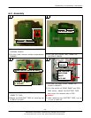
6-2. Assembly
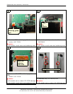
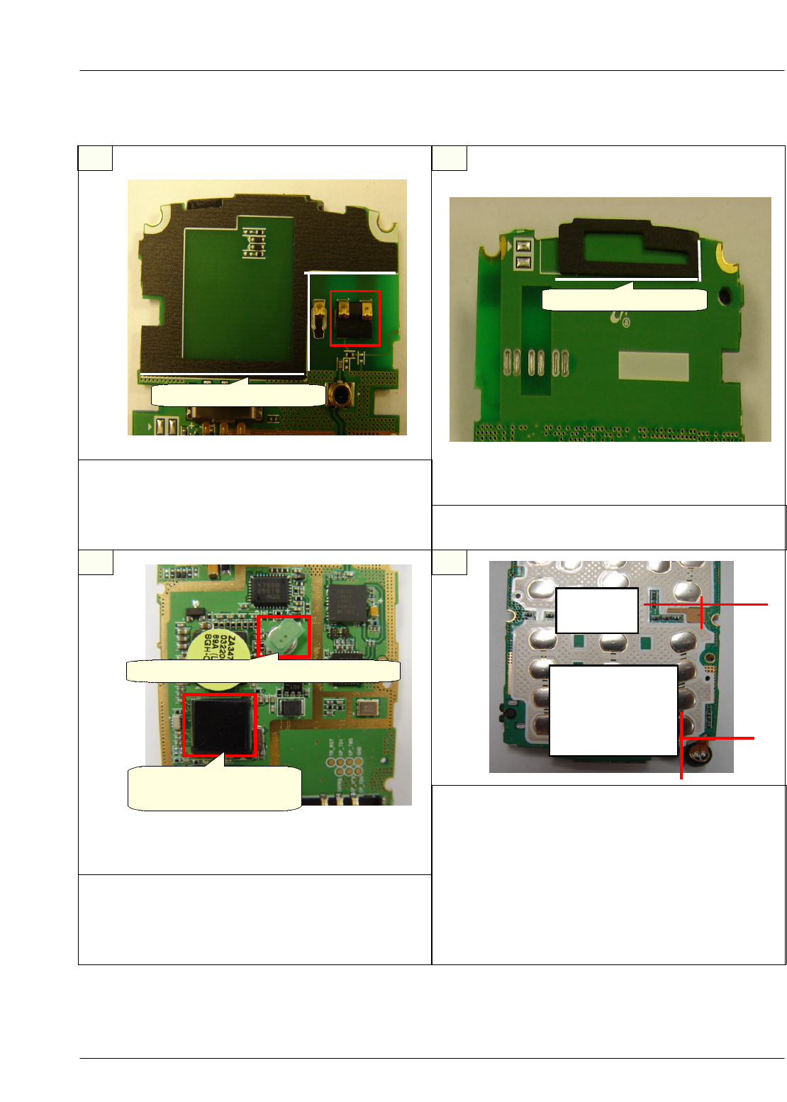
1) Fix into SILK GUIDE LINE, attach the
RECEIVER PORON.
1)Attach the CUSION ROBBER on ceter of
AGERETCCHIP.
2)Attach the ELECTRIC TAPE for covering top
of BACK UP BATT.
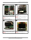
1) Fix into PCB GND corner, Attach the
SHIELD GARSKET.
2) Fix into outline of DOME SHEET and PCB
GRD corner, Attach the ELECTRIC TAPE
and cover the reverse side of PCB
※
caution
1) After attaching the ELECTRIC TAPE, rup up
it not to take off.
1
43
2
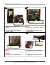
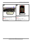
1)fix into silk guide line,Attach the CUSION
INTENNA PORON
2)fix into undet intenna contact shape,attach
ROBBER.
COVER TOP OF BACK UP BATT
ATTACH THE PART
OF CENTER
PCB OUTLINE
AND DOME
SHEET
OUTLINE
PCB GND
CORNER
SILK GUIDE LINE
SILK GUIDE LINE


