


9
Installation
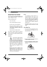
4. Route the adapter’s cord through the
strain relief slot on the bottom of the
base.
5. Plug the adapter into a standard AC out-
let.
6. Lift the base’s antenna to a vertical posi-
tion.
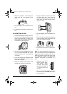
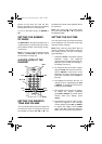
On a Wall Plate or Wall
1. Insert the two tabs at the top of the nar-
row end of the supplied bracket into the
base’s upper tab slots as shown, then
press down on the bracket’s latches and
insert them into the lower slots.
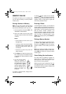
2. Plug one end of the supplied short mod-
ular cord into the
TEL
LINE
jack on the
back of the base as in “On a Desk Top”
on Page 8.
3. Insert the supplied AC adapter’s barrel
plug into the
DC IN 9V
jack as in “On a
Desk Top” on Page 8.
4. Route the adapter and modular cords
through the grooves on the bracket.
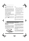
5. Plug the modular cord’s other end into
the wall plate jack, then align the
bracket’s keyhole slots with the wall
plate studs and slide the base down-
ward to secure it.
6. Plug the adapter into a standard AC out-
let.
7. Press and lift out the handset holder, flip
it over as shown, then snap it back into
place so it holds the handset.
8. Lift the base’s antenna to a vertical posi-
tion.
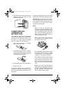
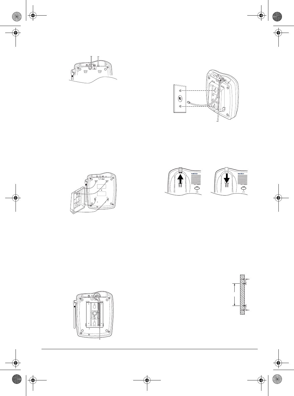
Note:
To mount the telephone directly on a
wall, you need two screws (not supplied) with
heads that fit into the keyhole slots on the
bottom of the base. Follow the steps under
“On a Wall Plate or Wall,” then apply these
additional instructions for placement on a
wall.
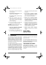
1. Drill two holes 3
15
/
16
inches (100 mm) apart.
Then thread a screw
into each hole, letting
the heads extend about
5
/
16
inch (8 mm) from
the wall.
2. Plug one end of the supplied long modu-
lar cord into the
TEL
LINE
jack at the
back of the base.
3
15
/
16
5
/
16
43-3805.fm Page 9 Wednesday, May 17, 2000 3:48 PM