


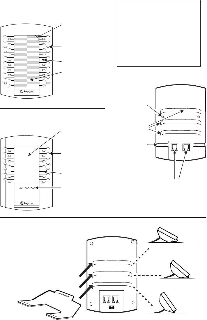
Connecting the Base Stand*
Fully insert the stand into one of
the slots on the back of the
Expansion Module. The slot you
choose determines the angle of
the Expansion Module. The
phone and Expansion Module
should be at the same angle.
*For wallmount installation, an optional accessory is available. For more information, contact your reseller.
VVX Color Expansion Module
Features
VVX Expansion Module
Features
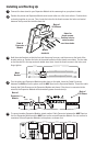
Back
(either model)
AUX 1AUX 2
Auxiliary Ports. Connect the Cable
Connector to one of these ports, and
to an Auxiliary Port on the phone or
another Expansion Module.
Cable groove
(one on each side) to
hold Cable Connector
in place
Slots for
base stand
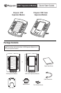
Line Keys
LED Indicators
Plastic cover overlaying
paper template.
Write phone lines, presence
contacts or speed dials
on the template.
Cut out in cover for easy
cover removal
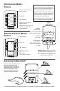
Line Keys
LED Indicators
Page Keys. Press a
page key to
display more Line Keys.
Color Display
Note: The paper module has a plastic
cover that overlays a paper template. To
remove or insert the template, place the
tip of a paperclip under the slot at the
top-right corner of the cover, lift the cover
off, and remove or insert the template. To
re-attach the cover, align the six tabs on
either side of the cover with the
corresponding indents on the Expansion
Module, and bend the cover into place.
Holes for
thumb screws
(one on each side)
to anchor metal bracket