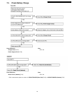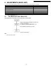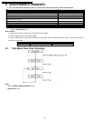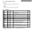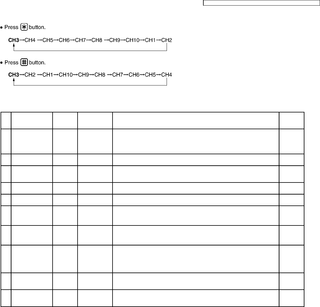
9.2. How to change the channel
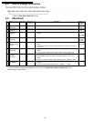
9.3. Adjustment
Adjustment Items Test Mode Adjustment
Point
Procedure Check or
Replace
Parts
(A) Battery Low
Confirmation
3ch Talk - 1. Set the power supply voltage to DC3.60V, and confirm so that the reading
of oscillosope is High.
2. Set the power supply voltage to DC 3.40V, and confirm so that the
reading of oscilloscope is Low.
IC1
(B) TX VCO
Voltage
3ch Talk T6 1. Adjust T6 so that the reading of the Digital Voltmeter is 1.0V ± 0.1V. IC1, X1,
T6
(C) RX VCO
Confirmation
3ch Talk -
• • Confirm RX VCO voltage so that the reading of the Digital Voltmeter is
2.9V ± 0.5V.
IC1, X1,
T6
L6, C24
(D) TX Frequency
Adjustment
3ch Talk VC1
• • Adjust VC1 so that the reading of the frequency counter is 39.875MHz ±
0.1KHz.
IC1, VC1
DPX1, T5
(E) TX Power
Adjustment
3ch Talk T5
• • Adjust T5 so that the reading of the RF VTVM (50Ω load) is 5dBm ±
1dBm.
DPX1, Q5,
T5
(F) RX Sensitivity
Adjustment
(2nd IF output)
3ch Talk T3 1. Apply -60dBm output from S.S.G. (modulation frequency 1KHz, dev.
0KHz).
2. Adjust T3 so that the reading of RF VTVM is more than 15mV.
DPX1,
T3,IC1,
CF1, CF2
(G) Noise Squelch
Confirmation
3ch Talk - 1. Measure the SSG output level when the noise squelch changes from Low
to High. (modulation frequency 1KHz, dev.3kHz)
2. Confirm so that the SSG output level is -105dBm.
IC1, DPX1
(H) Speaker
Output Level
confirmation
3ch Talk - 1. Apply -60dBm output from S.S.G. (modulation frequency 1KHz, dev.
3KHz).
2. Confirm so that SP output level is 120mV ± 30mV.
(distortion: less than 7%) (volume High).
IC1
(I) Mic Modulation
Factor
Confirmation
3ch Talk - 1. Apply a MIC signal (1KHz, 2.4mV at 600Ω load).
2. Confirm so that the reading FM Deviation Meter is 3.1KHz ± 0.4KHz.
IC1, DV1
(J) Data
Modulation
Confirmation
3ch Talk -
• • Confirm so that the reading of the FM Deviation Meter is 5kHz ± 1kHz.
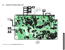
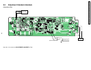
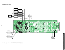
The connections of adjustment equipment are as shown in Adjustment Standard (Handset) (P.28).
SSG Frequency: 30.175 MHz
27
KX-TC1205RUB / KX-TC1205RUW / KX-TC1205RUS / KX-TC1205RUF


