


Part No. 091-296-00 Rev. B
8
Sends 1, 2, 5 and 6 when the Shift switch is engaged, and
Aux Sends 1 and 2 shall have a pre/post switch; 4 rotary
equalization (EQ) controls: ±15dB fi xed 12kHz shelving gain,
±15dB midrange peaking gain, 100Hz – 8kHz midrange fre-
quency, and ±15dB fi xed 80Hz shelving; 1 75Hz 18dB/oct.
Low Cut fi lter switch; 1 rotary Pan control, 4dB attenuation
panned center; 1 Mute switch; 1 dual-mode Solo switch (AFL
or PFL, globally switched); 3 output Assign switches, deliver-
ing the channel’s signal, relative to its Pan setting, to the
Main L-R Mix, Submasters 1–2 and Submasters 3–4; and
1 channel Fader, providing up to 10dB above unity gain.
Additionally, each channel shall include two LED indicators; a
–20/Solo LED acting as a Signal Present indicator by fl icker-
ing and as a channel Solo indicator by glowing steadily; and
an OL/Mute LED, acting as an overload indicator by fl ickering
and as a channel Mute indicator by glowing steadily.
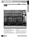
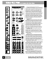
5. MIXER OUTPUT SECTION. The mixer shall have 1 Main
Mix stereo fader, providing up to 10dB gain; 4 Submaster
mono faders, each providing up to 10dB gain; independent
left and right Assign to Main Mix switches for each Submas-
ter; 1 Control Room/Phones level rotary stereo control, pro-
viding up to 10dB gain; 1 Source Matrix, including 4 switches
to deliver any combination of stereo signals to the Control
Room, Phones and Meters, including Main Mix, Submasters
1–2, Submasters 3–4 and Tape, which shall be replaced
by solo signals resulting from the engagement of any Solo
switch; 1 rotary stereo Tape In level control, providing up to
20dB gain; 1 Tape to Main Mix switch; 1 Solo Mode switch
to globally determine solo type (pre-fader listen or after-fader
listen, in place); 1 rotary stereo Solo level control, providing
up to 10dB gain; 4 rotary stereo Aux Return level controls,
providing up to 20dB gain; two Effects to Monitor rotary
controls, providing up to 15dB gain, delivering summed Aux
Return 1 or 2 signals to Aux Send 1 or 2, respectively; an Aux
Return 3 Assign switch, used in conjunction with a 1–2/3–4
switch, delivering Aux Return 3 signals to one output pair,
including Main Mix, Submasters 1–2 and Submasters 3–4; an
Aux Return 4 to Control Room/Phones Only switch; a global
Aux Return Solo switch with associated LED; 2 rotary Aux Send
Master controls for Aux Sends 1 and 2, providing up to 10dB
above unity gain; a Solo switch with associated LED for each of
Aux Sends 1 and 2; a blinking master Solo indicator LED, a Level
Set LED, indicating a PFL solo condition, a Power indicator LED;
and a Phantom Power indicator LED.
6. METERING. The mixer shall include 1 stereo 12-seg-
ment LED meter with points at –30, –20, –10, –7, –4, –2, 0,
+2, +4, +7, +10 and +28dB. The source signals for the meters
shall be the same signals selected in the Source Matrix, and
a solo condition shall replace the Source selection with the
soloed channel(s). The meters shall be calibrated so that a
0dBu signal at the Control Room output shall be indicated as
0dB on the meters, ±1LED.
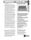
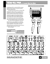
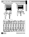
7. PHYSICAL CONFIGURATION. The mixer shall be made
of steel and aluminum, painted dark gray and black with
light gray graphics. The mixer shall weigh 20 lbs, 0 oz (9.1
kg). Included rackmount brackets shall allow the mixer to be
mounted in a rack system, with either the chassis surface
or the control knobs’ tops to be fl ush with the rack rail.
Additionally, the jackfi eld portion of the mixer, referred to
as the Pod, shall be adjustable in three different positions;
Desktop Mode (stock confi guration), with jackfi eld connec-
tions to rear as seen laying horizontally on a table; Rackmount
mode, with the jackfi eld connections to the rear of the rack
when mounted vertically; and RotoPod mode, requiring an
RP1604-VLZ RotoPod Bracket (not included), with jackfi eld
connections on the same plane as the faders. Dimensions
of the mixer shall be, in Desktop Mode, 17.3" (442mm) in
width, 17.6" (447mm) in depth, and 5.0" (127mm) in height;
in Rackmount Mode, 19" (483mm) in width (including rack
rails) 13.0" (325mm) in height, and 9.3" (236mm) in depth;
in RotoPod Mode (using optional brackets sold separately)
19" (483mm) in width (including rack rails), 17.9" (455mm) in
height and 6.6" (168mm) in depth.
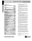
8. SPECIFICATIONS. In addition to specifi cations already
cited, the mixer shall meet or exceed the following specifi ca-
tions. Frequency response, microphone input to any output,
20Hz to 60kHz, +0dB/–1dB; Total Harmonic Distortion (THD),
any input to any output, 1kHz @ +14dBu, 0.0007%; Equiv-
alent Input Noise (EIN), microphone input to insert send,
–129.5dBm; Common Mode Rejection (CMR), microphone
input to insert send, maximum gain, 1kHz, better than 90dB;
Typical Main Output noise, all channels assigned, odd chan-
nels panned left, even channels panned right, all faders down
–100dBu; Signal to Noise ratio, ref +4dBu operating level,
90dB; Attenuation, ref. 0dB @ 1kHz, Main Mix level control
down, –85dBu; Channel Mute engaged, –84dBu; Channel
Gain control down, –83dBu; Input impedance, microphone
inputs, 1.3 kΩ; Channel Insert return, 2.5 kΩ; All other inputs,
greater than 10 kΩ; Output impedance, Tape Out, 1.1 kΩ; All
other outputs, 120Ω.
The mixer shall be a Mackie 1604-VLZ PRO.
LOUD Technologies continually engages in research related to product improvement. New material,
production methods, and design refi nements are introduced into existing products without notice
as a routine expression of that philosophy. For this reason, any current LOUD Technologies product
may differ in some respect from its published description, but will always equal or exceed the
original design specifi cations unless otherwise stated. ©1999-2004 LOUD Technologies Inc. All
rights reserved.
www.mackie.com
16220 Wood-Red Road NE, Woodinville, WA 98072 USA
800.898.3211, fax 425.487.4337, sales@mackie.com
UK +44.1268.570.808, fax +44.1268.570.809, uk@mackie.com