


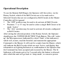
select and activate one (1) of the eight (8) possible Bell Circuits or all
Bell Circuits (those circuits not defined as Clock Control Circuits) in
the Master Controller. The selection made will execute when the push
button on the Remote Bell Ringer’s Panel is pressed, and those circuits
will remain activated until the button is released.
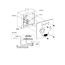
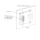
The Assembly of the Remote Bell Ringer consists of an Electronic
Circuit suspended beneath a cover plate for a double-gang switch-type
electrical box (not supplied with the product). The Circuit includes a
low-power MicroProcessor, a method of selecting the ‘Address’ of the
Master to be remotely controlled, and a 4-screw Terminal Block for
Installer Interconnect. Two screws of the Terminal Block are for
attachment of the Twisted-Pair (Cat-3 typical) low-voltage Network
Communications Cable to the Master’s RS-485 Port. The other two
screws are to be used for supplying 9-24V AC/DC as continuous power
source to the unit.
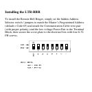
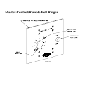
On the face of the cover plate are a 9-position Rotary Switch (to select
the Circuits to be made ‘Active’), a Push Button to send the Command
to the Master, and an array of lighting Status Indicators by which the
Operator can receive confirmation from the Master that the Manual
Bells Command has been accepted and acted upon.