


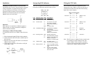
Interpreting LED Indicators
There are six diagnostic LED indicators provided on the
transceiver to indicate the operation status as below:
LED Operation status State Interpretation
Power Power status On Transceiver is on.
Off Transceiver is off.
Link UTP link status On The UTP link is ok or link
test function is disabled.
Off No UTP link or UTP link is
faulty.
Blink UTP link is faulty.
TRX Transmission status Blink Transmission is in operation.
Off No transmission.
On Normal, if large transmission is
in operation.
Problem, if no transmission.
RCV Receiving status Blink Receiving data packet
Off No packet is being received.
On Normal, if heavy traffic load.
Normal, if no UTP link.
Problem, if no network traffic.
COL Collision status Off No collision occurs.
Blink There is presence of collisions.
POL Polarity reversal Off There is no polarity reversal
problem detected on the UTP
cable.
On Polarity reversal problem
exists on the receiving pair
of the UTP cable.
Wiring the UTP Cable
How to install the UTP cable is determined by the
characteristics of the 10Base-T UTP port of the device
connected at the other end of the cable. The following
figure shows some examples:
Wiring for the UTP cable
Pin Pin
1 ------------ 1
Transceiver 2 ------------ 2 10Base-T hub's
3 ------------ 3 IN jack
6 ------------ 6
Pin Pin
1 ------------ 3
Transceiver 2 ------------ 6 10Base-T hub's
3 ------------ 1 OUT jack
6 ------------ 2
Pin Pin
1 ------------ 3
Transceiver 2 ------------ 6 Computer's
3 ------------ 1 10Base-T port
6 ------------ 2
Pin Pin
1 ------------ 3
Transceiver 2 ------------ 6 Transceiver
3 ------------ 1
6 ------------ 2
Note: The OUT jack of a 10Base-T hub is normally used
for connection to another 10Base-T hub. The
vendor's 10Base-T hub, sometimes, provides a
crossover option to set the jack as an IN jack for
connection to a 10Base-T Ethernet station.
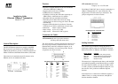
Installation
Attaching to an Ethernet device via an AUI cable
The Ethernet device can be a network interface controller,
wiring concentrator, or repeater that provides an AUI
port. For attaching to such device, an AUI cable of
appropriate length is required. The following figure
illustrates the connection of the transceiver and an
Ethernet device via an AUI cable.
Important:
If the transceiver is attached to an Ethernet repeater, a
10Base-T hub, or a wiring concentrator, the SQE test
function should be disabled.
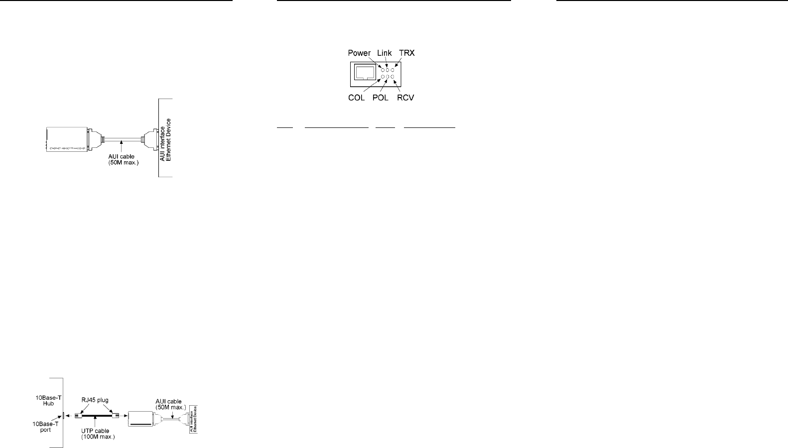
Connecting to a 10Base-T Ethernet Hub
To connect the transceiver to a 10Base-T hub, follow the
steps:
1. Select an appropriate length UTP cable for the connection.
2. Connect one end of the UTP cable to the RJ45 jack of
the transceiver.
3. Route the free end of the UTP cable to area where the
10Base-T hub is located.
4. Connect the free end of the UTP cable to an IN jack
on the 10Base-T hub.