


Intel Desktop Boards D865GRH Product Guide
viii
Figures
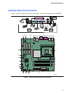
1. Desktop Board D865GRH Components....................................................................... 13
2. Location of Standby Power Indicator............................................................................ 22
3. Installing the I/O Shield ................................................................................................ 28
4. Location of Mounting Screw Holes............................................................................... 29
5. Installing a Processor................................................................................................... 30
6. Connecting the Processor Fan Heat Sink Cable to the Processor Fan Connector ....... 31
7. Installing a Memory Module ......................................................................................... 32
8. Dual Configuration Example with Two DIMMs.............................................................. 33
9. Dual Configuration Example with Four DIMMs............................................................. 33
10. Removing the AGP Card.............................................................................................. 35
11. Connecting the IDE Cable............................................................................................ 36
12. Connecting the Serial ATA Cable................................................................................. 37
13. Internal Headers .......................................................................................................... 38
14. Back Panel Audio Connectors for 6-Channel Audio with Jack Sensing ........................ 41
15. Location of Hardware Control Headers and Power Connectors.................................... 42
16. PCI Bus Add-in Card and Peripheral Interface Connectors .......................................... 44
17. Location of the BIOS Configuration Jumper Block........................................................ 45
18. Back Panel Connectors................................................................................................ 47
19. Removing the Battery................................................................................................... 51
Tables
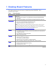
1. Feature Summary ........................................................................................................ 11
2. Desktop Board Components ........................................................................................ 14
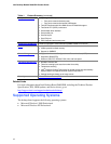
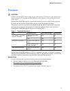
3. Supported Processors.................................................................................................. 15
4. RJ-45 10/100/1000 Gigabit Ethernet LAN Connector LEDs ......................................... 18
5. Front Panel Header (J9J1)........................................................................................... 39
6. USB 2.0 Headers (J9F1 and J9H1).............................................................................. 39
7. Front Panel Audio Header Signal Names (J9A2) ......................................................... 40
8. Jumper Settings for the BIOS Setup Program Modes (J9J4)........................................ 45
9. BIOS Setup Program Menu Bar ................................................................................... 57
10. BIOS Setup Program Function Keys ............................................................................ 58
11. Maintenance Menu....................................................................................................... 58
12. Main Menu ................................................................................................................... 59
13. Advanced Menu........................................................................................................... 60
14. PCI Configuration Submenu......................................................................................... 61
15. Boot Configuration Submenu ....................................................................................... 62
16. Peripheral Configuration Submenu .............................................................................. 63
17. ATA/IDE Configuration Submenu................................................................................. 65
18. SATA and PATA Submenus ........................................................................................ 66
19. Diskette Configuration Submenu.................................................................................. 68
20. Event Log Configuration Submenu............................................................................... 69
21. Video Configuration Submenu ..................................................................................... 70
22. USB Configuration Submenu ....................................................................................... 71
23. Chipset Configuration Submenu................................................................................... 72
24. Hardware Management................................................................................................ 74
25. Hardware Monitoring Submenu.................................................................................... 75
26. Security Menu.............................................................................................................. 76