3
INTRODUCTION
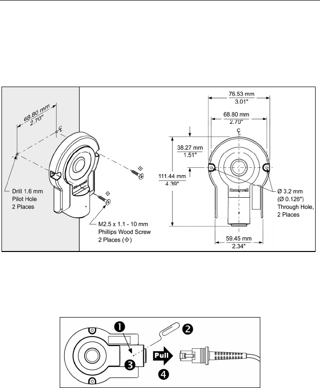
Mounting Specifications
1. Drill two, 1.6 mm pilot holes in the mounting surface. The pilot holes should
be located on a common centerline and be spaced 68.80 mm (2.70") apart.
2. Secure the access point device to the mounting surface with the
M2.5 x 1.1 - 10 mm, Phillips wood screws provided with the access point.
Figure 2. Mounting Specifications
Cable Removal
Turn off power to the host system before removing the cable from the access
point device. If the cable is a PowerLink cable, disconnect the power supply on
the cable.
Figure 3. Cable Removal
1. Locate the small pinhole on the top of the access point device
(see figure above).
2. Bend an ordinary paperclip into the shape shown above.
3. Insert the paperclip into the pinhole on the device. Apply pressure to
release the connector’s lock.
4. Pull on the cable’s strain-relief to remove the cable.


