


Guardian Telecom Inc.
Installation and Operation
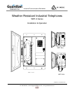
Model WRT-A
Page 7
Field Repairs & Adjustments
Field repairs may only be carried out by qualified technicians using OEM parts.
Substitution of parts voids warranty and may pose a hazard to users of the
equipment.
See: Replacement Parts
• Disconnect the telephone from Tip and Ring power supplied by the PABX
or central office before attempting repairs.
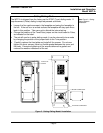
• Loosen the five captive screws in the faceplate and swing the faceplate to
the left. If the set is on a vertical surface the faceplate will stay open like a
book in this position. Take care not to disturb the internal wiring.
See: Figure 4 - Fuse
Replacement
• Perform the necessary repairs or adjustments.
• Carefully replace the front plate and install all five screws. Do not over
tighten the cover screws, there is a flexible gasket between the cover and
the body. Excessive tightening of the screws deforms the gasket and
reduces the weather resistance of the set.
Note: Ensure that
connections are secure
before replacing
faceplate.
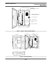
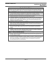
Fuse Replacement
• Remove the old fuse by pushing in the end cap of the fuse holder and
turning counterclockwise to open. Insert a new 0.25 amp, 250Volt, 3AG
fast blow fuse and close the fuse holder.
WARNING!
• Replace only with a 0.25 amp 250V 3AG fast blow fuse. Failure to do so
will void the warranty.
• If, on reconnecting power, the fuse fails, check the telephone system
wiring. The fuse protects the Tip and Ring line from the telephone system.
It is usually powered at 48 volts DC and must not be connected to 120 volts
AC.
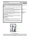
FUSE
0.25 AMP .3AG
FAST BLOW
GROUND
GROUND CONNECTION
TIP & RING CONNECTION
Figure 4 - Fuse Replacement