


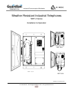


Guardian Telecom Inc.
Installation and Operation
Model WRT-A
Page 5
Installing the WRT-A
• WRT-A telephones shall be installed by qualified service personnel.
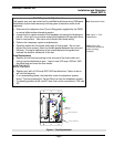
• The WRT-A is set to tone dialing when shipped. If pulse dialing is required
see the section on Setting Dialing Mode.
• Follow all appropriate electrical codes and use only approved electrical
fittings for the installation.
See: Figure 3 - Setting
Dialing Mode &
Installation
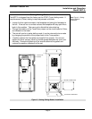
• Choose a wall location that is free of obstructions and permits space for
wiring.
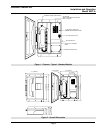
• Ensure mounting can support 6.5 lbs (2.95 kg) plus any additional,
foreseeable load.
See: Figure 2 - Overall
Dimensions
• Ensure that none of the electrical connection circuits are live.
Mounting
• Use the template or the unit itself to locate and drill holes for mounting
screws.
• Secure the unit to the wall.
Hard Wiring the WRT-A to the Telephone System
• Remove the wiring access cover plate.
• Install a suitable conduit hub or cable gland in the cable entrance hole.
• Bring cable into the enclosure through the cable entrance and attach
individual wires from the exchange – Tip/Ring/Ground – to the surge
arrestor (Tip & Ring are not polarity sensitive).
WARNING
Protective earthing terminal of the phone shall be properly hardwired
to a protective earth system.
• Replace the wiring access cover plate.
Final Check
• Check the set visually for loose screws and trapped wires. Check that the
handset hangs freely in the cradle and that the handset cord is not trapped
by the door.
• Check that the faceplate is snug to its gasket, paying particular attention to
the area around the cradle. Check that the door closes flush to the housing.
• Test the unit by calling to and from another unit on the exchange.
Operation
• Once your Model WRT-A Telephone has been properly installed and
energized, operation is identical to most other single line telephones.
WARNING
Due to magnetic fields, it is possible that dangerous objects may get trapped
within the earcap region of this device.