


Guardian Telecom Inc.
Installation and Operation
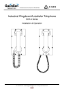
SCR-A Series
Page 7
Installing the SCR-A
• SCR-A telephones shall be installed by qualified service personnel.
• Follow all appropriate electrical codes and use only approved electrical
fittings for the installation.
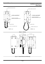
• Choose a wall location that is free of obstructions and permits space for ½”
NPT conduit runs.
See:Figure 2 - Overall
Dimensions & Mounting.
• Ensure mounting can support 4 lbs. (1.8 kg) and any additional foreseeable
load.
• Remove the eight (8) cover screws from the front of the unit and carefully
remove the front cover assembly. NOTE that the handset and all
electronics are attached to the front plate. The front cover may be
separated from the back box by disconnecting the harness plugs.
• Attach the back box to the wall at the desired location using four (4) #8
screws. If weather resistance is important in your application select
washers that will assist in sealing the mounting holes.
• Install a suitable conduit hub or cable gland in the cable entrance hole at the
bottom of the unit.
• Connect an approved earth ground to the terminal block.
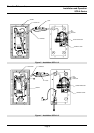
• Bring cable into the enclosure through the cable entrance and attach
individual wires from the exchange – Tip/Ring/Ground – to the surge
arrestor (Tip & Ring are not polarity sensitive).
See: Figure 3 -
Installation SCR-11-A &
Figure 4 - Installation
SCR-41-A.
WARNING
Protective earthing terminal of the phone shall be properly hardwired
to a protective earth system.
• Apply power to the system.
• Test the unit by calling to and from another unit on the exchange.
Operating the SCR-A
• The SCR-A Ringdown/Autodialer phone is designed for automatic calling
simply by removing the handset from the cradle.
WARNING
Due to magnetic fields, it is possible that dangerous objects may get trapped
within the earcap region of this device.