


Guardian Telecom Inc.
Installation and Operation
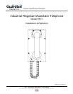
Model HR71
Page 5
Installing the HR71
• Follow all appropriate electrical codes and use only approved electrical
fittings for the installation.
• Choose a wall location that is free of obstructions and permits space for ½”
NPT conduit runs.
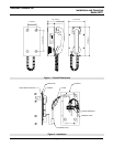
See: HR71 Drawing,
Figure 1 - Overall
Dimensions.
• Ensure mounting can support 4 lbs. (1.8 kg) and any additional foreseeable
load.
• Remove the eight (8) cover screws from the front of the unit and carefully
remove the front cover assembly. NOTE that the handset and all
electronics are attached to the front plate. The front cover may be
separated from the back box by disconnecting the harness plugs.
• Attach the back box to the wall at the desired location using four (4) #8
screws. If weather resistance is important in your application select
washers that will assist in sealing the mounting holes.
See: HR71 Drawing,
Figure 1 - Overall
Dimensions.
• Connect cable or conduit (1/2 inch trade size) to the entrance at the bottom
of the unit.
• Connect an approved earth ground to the terminal block.
• Bring cable into the enclosure through the conduit entrance and attach
individual wires from the exchange (Tip/Ring/Ground) to the connector (Tip
& Ring are not polarity sensitive). If a conduit hub is used, ensure it is
grounded to the ground stud.
• Apply power to the system.
• The HR71 Telephone may be supplied with an optional Auto Dialer or
dialing may be configured by the PABX. If an Auto Dialer is ordered with
the HR71, refer to the manual for the Auto Dialer for instructions on
programming and for compliances.
• Test the unit by calling to and from another unit on the exchange.
Operating the HR71
• The HR71 Ringdown/Autodialer phone is designed for automatic calling
simply by removing the handset from the cradle.