


Guardian Telecom Inc.
Installation and Operation
Model CIT-40
Page 6
Installing the CIT-40
• If Pulse dialing is required refer to the section on Setting Dialing Mode.
• Follow all appropriate electrical codes and use only approved electrical
fittings for the installation.
See:Setting Dialing
Mode
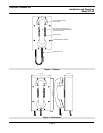
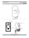
• Choose a wall location that is free of obstructions and permits space for
cable or conduit runs.
See: Figure 2 -
Dimensions
• Ensure mounting can support 4lbs (1.8kg) and any additional load to which
the telephone may be subjected.
• Ensure that none of the electrical connection circuits are live.
• Bring Tip, Ring and Ground wiring to the location where the wiring access
opening in the back of the CIT-40 will be when the telephone is installed.
Tip: The CIT-40 may be
wired directly to the
terminal block or an
RJ11 connector may be
used.
• Remove the eight (8) cover screws from the front of the unit and carefully
remove the front cover assembly. NOTE that the handset and all
electronics are attached to the front plate. The front cover may be
separated from the back box by disconnecting the harness plug.
Tip: Use the driver bit
provided to remove the
tamper resistant screws.
• Use the enclosure as a template to locate and drill holes for #8 or M4
mounting screws or other suitable attachments.
See: Figure 3 -
Mounting.
• Feed Tip, Ring and Ground wiring through the wiring access opening and
secure the unit to the wall.
• Attach individual wires from the exchange (Tip/Ring/Ground) to the terminal
strip (Tip & Ring are not polarity sensitive), or plug the RJ11 connector into
the socket if this termination method was chosen. Even if an RJ11
connector is used an approved earth ground must still be provided to the
ground connection on the terminal strip.
• Ensure all connections are tight, then replace and secure the cover.
• Connect the telephone into the system.
See: Figure 4 - Electrical
Connections
Note: an approved earth
ground must be
connected to the ground
position on the terminal
strip regardless of Tip
and Ring wiring method.
• Test the unit by calling to and from another unit on the exchange.
Operation
• Once the Model CIT-40 Telephone has been properly installed and
energized operation is identical to most other single line telephones.
Field Repairs
Note: The only field repair permitted is the replacement of fuses and changing
the Tone/Pulse setting. All other repairs or alterations must be carried out by
Guardian Telecom or an Authorized Service Depot. See Warranty and
Disclaimer for details.
See: Figure 4 - Electrical
Connections