


Firmware version 1.0.0.8 DP715/DP710 User Manual Page 10 of 52
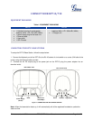
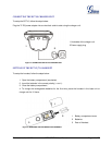
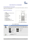
Table 2: DEFINITIONS OF THE DP715 CONNECTORS
DC 6V
Power adapter connection.
NETWORK PORT
(RJ-45)
10/100Mbps RJ-45 port to connect to the network.
RESET
Factory Reset button: Press for 7 seconds to reset factory default settings.
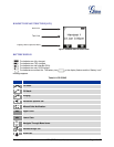
Table 3: BASIC DEFINITIONS OF THE DP715 LEDS PATTERN
LEDs
POWER LED
Indicates Power. Remains ON when power is connected
NETWORK
Indicates Access to the Network. Remains ON while there is Access to the Network
REGISTERED
Indicates if the SIP accounts are registered
CALL
Indicates status of active calls.
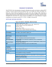
Table 4: ADVANCED DEFINITIONS OF THE DP715 LEDS PATTERN
Pattern
Number
Condition
LED
LED Behavior
LED-01
Device has normal power
POWER
ON
LED-02
Power Error: Power is removed from the device or power
supply with improper voltage is plugged in
POWER
OFF
LED-03
Device has normal LAN connection and has obtained an
IP address
NETWORK
ON
LED-04
Link Down
Note : This is the default state while the device is booting.
NETWORK
Blink (1s on/ 1s off).
LED-05
Link Up but no IP Address
NETWORK
Blink ( 0.25s on/ 0.25s
off )
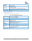
LED-06
All configured SIP accounts are registered
REGISTERED
ON
LED-07
SIP accounts are in the process of registering
REGISTERED
Blink ( 1s on/ 1s off )
LED-08
Device is booting, application has not started.
REGISTERED
Blink ( 0.25s on/ 0.25s
off )
LED-09
Registration Error - ANY SIP account experiences
registration failure.
REGISTERED
0.25sec ON/ 0.25sec OFF
LED-10
Call is active. Any DECT handset is in an active call with
an external line.
CALL
ON
LED-11
No active call.
CALL
OFF