


IPI 100 Series • Installation Instructions
2
IPI 100 Series Installation Instructions, cont’d
Installation
Before installing your IPI 100, read the following publications, which can be found on the Extron website (www.extron.com):
“IPI 100 Series and IPI 200 Series User’s Manual”•
“IP Intercom System Frequently Asked Questions”•
W
Installation and service must be performed by authorized
personnel only. These products must be used with UL
approved grounded electrical boxes.
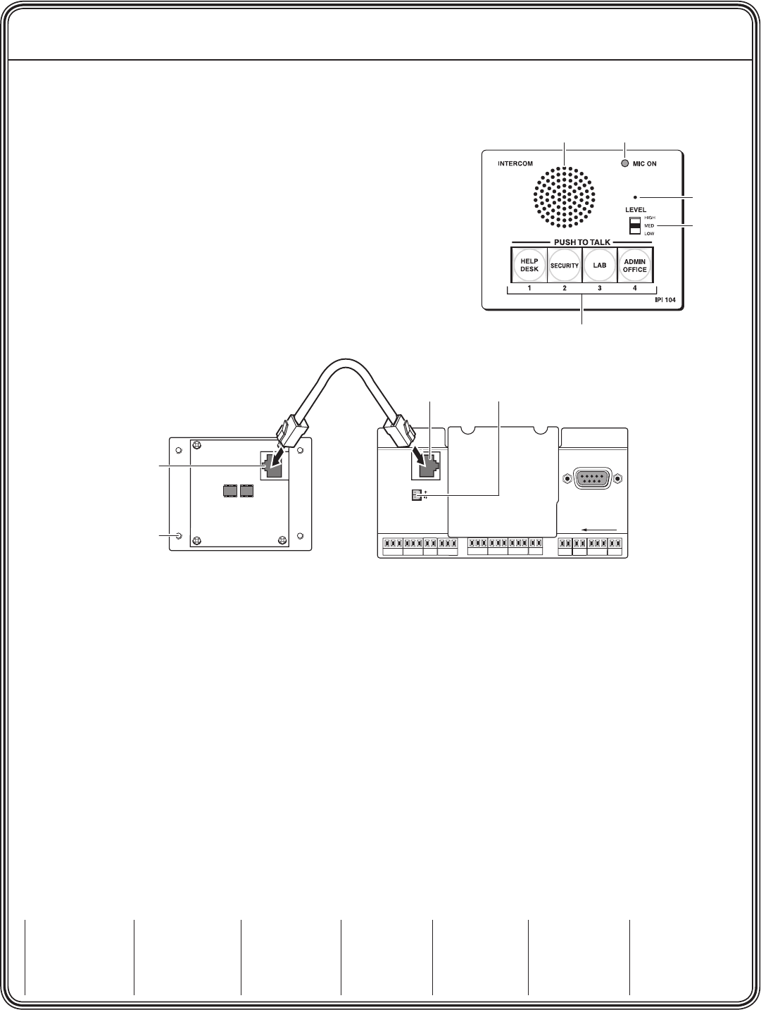
The front panel of the IPI 104 is shown at right. The front panel for the IPI 101
is the same, except there is only one button. The rear panels for both units are
identical and are shown in the illustration below.
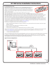
1. Determine which rooms will have IP Intercoms and PC HelpDesks and
where, in each room, they will be located. Ensure there is a network
connection for each intercom and each HelpDesk PC.
2. Connect the IPI to the MLC 226 IP controller, using the included 12 inch
(30.5 cm) network cable.
3. Cable the MLC 226 IP to other devices:
Connect the LAN port to the local network, using a standard network cable with an RJ-45 connector.•
If desired, cable the rear panel audio connector for local audio output.•
Cable other devices (control modules, SCP, and/or IR emitters) to the MLC as needed (for more information, see the •
MLC 226 IP User’s Manual, which is available on the Extron website (www.extron.com).
4. Install the IPI 100 unit and the MLC 226 IP into the wall box(es) or furniture.
5. Ensure the HelpDesk PC(s) are connected to the network, and power on the MLC(s) and PC(s).
6. Configure the MLC(s) as described in the MLC 226 IP User’s Manual and the Global Configurator Help File, which are
available on the Extron website (www.extron.com).
7. Install the Extron IP Intercom HelpDesk software, which is on the disk that shipped with the unit and is also available for
download from the Extron website (www.extron.com).
8. Use the IP Intercom HelpDesk software to configure all intercom units in the system. Full instructions can be found in
the IPI 100 Series and IPI 200 Series User’s Manual and also in the software’s Help File.
When the front panel button(s) light amber, the unit is correctly installed and configured. If the button(s) light red the unit has
not been correctly configured and you should check the IPI 100 Series and IPI 200 Series User’s Manual or the software’s Help
File.
Extron USA - West
Headquarters
+800.633.9876
Inside USA / Canada Only
+1.714.491.1500
+1.714.491.1517 FAX
Extron USA - East
+800.633.9876
Inside USA / Canada Only
+1.919.863.1794
+1.919.863.1797 FAX
Extron Europe
+800.3987.6673
Inside Europe Only
+31.33.453.4040
+31.33.453.4050 FAX
Extron Asia
+800.7339.8766
Inside Asia Only
+65.6383.4400
+65.6383.4664 FAX
Extron Japan
+81.3.3511.7655
+81.3.3511.7656 FAX
Extron China
+400.883.1568
Inside China Only
+86.21.3760.1568
+86.21.3760.1566 FAX
Extron Middle East
+971.4.2991800
+971.4.2991880 FAX
Speaker Microphone On LED
Microphone
Level Switch
Push To Talk Buttons
IPI 104 AAP Front Panel
HOST
CONTROL
R
1=DIGITAL I/O
2=Tx 3=Rx 5=GND
38400, N, 8, 1
PRESS TAB WITH
TWEEKER TO REMOVE
INTERCOM
AUDIO
OUT
LAN
IPI 101 AAP or IPI 104 AAP
Rear Panel
MLC 226 IP Rear Panel
AAP Mounting Screws (4)
Intercom Port
Intercom Port Audio Output