


Power Jack - Connection point for the 12-volt, negative ground power source.
Remote Control Unit Jack - Connection point for the remote control unit if it is used. This jack is optional with front
mount transceivers.
Accessory Jack - Connection point for the ignition sense input and optional accessories such as an external speaker
(4-ohm, 12-watt) and horn/light alert.
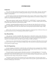
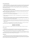
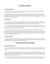
PHONE SYSTEM/GROUP
MONITOR
ENCRYPTION ENABLED
ALPHANUMERIC DISPLAY
SYSTEM NUMBER
STATUS DISPLAY
GROUP NUMBER
DISPLAY
NOTE: The display backlight may turn on with transceiver power or it may be manually turned on and off with the
BKLHT option switch or Menu mode “BACKLIGHT” parameter (see page 18).
System Number - Indicates the currently selected system number. System numbers up to 99 can be programmed.
Group Number - Indicates the currently selected group number. Group numbers up to 11 (Multi- Net) or 10 (LTR/
conventional) can be programmed.
Alphanumeric Display - This 10-character area of the display indicates a unique identification for the selected group.
For example, “GAS TRUCK” could be displayed when a certain group is selected. It also displays various error and
status messages.
Status Display - These two characters indicate the following status information:
Rotating clock-like symbols in both positions indicate that scanning is occurring.
This symbol in the left position indicates that the displayed system is in the scan list. Likewise, this symbol in the
right position indicates that the displayed group is in the scan list.
This symbol in the right position indicates that group scanning is occurring.
P1/P2 - When a conventional system is selected, “P1” indicates that a message on a priority 1 group is being re-
ceived, and “P2” indicates that a message on a priority 2 group is being received. Refer to “Priority Group Sampling”
on page xx for more information.
ON/OF - When the menu mode is selected by the MENU switch, “ON” indicates that the displayed parameter is
active, and “OF” indicates that it is inactive.
- Indicates that the function controlled by the option switch above it is active. For example, this symbol below the
Scan switch indicates that the scan mode is enabled. Only certain switches require this indicator.
- Indicates that the displayed system/group is programmed for telephone or special calls.