


6. Telephone is then mounted according to procedure detailed in MOUNTING TO
MODULAR PLUG.
NOTE: If you encounter difficulty fitting the telephone body onto the screw, or the
telephone wobbles when installed, either tighten or loosen then screw to adjust.
MAKING AND ANSWERING CALLS
To get a dial tone or answer an incoming call, lift the handset.
To hang up, either replace the handset or simply press the HANDSET CRADLE.
IN CASE OF DIFFICULTY
If you are having problems with your telephone, try the following suggestion.
NO DIAL TONE
1. Make sure that all plugs are connected properly. Check the connections at the wall
jack, the telephone cabinet and handset.
2. Try another modular jack within your home which you know to be working properly.
CALLS CANNOT BE DIALED OR DIALED SLOWLY
Check to make sure that the DIAL MODE switch is in the correct position for the type
of service available in your area.
TELEPHONE DOES NOT RING
Check that RINGER CONTROL switch is not set to OFF.
If there are several telephones connected to the same line, try disconnecting some
of the other telephones. Having too many telephones connected to the same line can
cause low ringer volume or poor sound quality during calls.
CARE AND MAINTENANCE
Avoid rough treatment to the telephone. Do not drop the handset and always replace
it gently onto the cradle.
Clean only with a cloth slightly dampened with water only. Do not use detergent,
waxes, solvent, spray, alcohol or excessive water.
LAST NUMBER REDIALING
To redial the last number dialed, momentarily depress the center disk.
Set Up
DIAL MODE
Locate the DIAL MODE switch on the rear of the telephone body. Slide the switch to
Tone unless you have Dial-Pulse (Rotary) telephone service in your area in which
case, slide the switch to the PULSE position.
RINGER CONTROL
The RINGER CONTROL switch is on the rear of the telephone body. It allows you to
turn the ringer OFF or set it to ring at either LOW or HIGH volume. You can still make
or receive calls with the ringer in OFF position, however, you will not hear the incoming
ring.
RECEIVER VOLUME
The RECEIVER VOLUME CONTROL switch, located on the rear of the telephone
body, allows you to adjust the volume of the receiver earphone from LO, MID and HI.
HANDSET CORD
To assemble, insert one end of handset cord into the HANDSET CORD JACK and
the other end to the HANDSET CORD JACK located on the left side of the telephone
body.
Installation
MODULAR WALL JACK
To install the telephone directly on a modular wall jack :
1. Connect the 15 inch line cord to the LINE CORD jack on the rear of the telephone
body.
2. Tuck the line cord into the channel on the cabinet rear.
3. Peel and stick the rubber pads on rear of telephone cabinet in designated areas.
4. Hold the telephone body up next to the modular jack and plug the line cord into this
jack.
5. Tuck the excess line cord into the recess provided on the rear of the telephone
body.
6. Line up the mounting holes of the telephone body with the mounting studs (screw
heads) on the modular jack or wall.
7. Push the telephone body against the wall jack and down until it is held securely in
place by the mounting studs.
WALL
If you are not mounting directly onto a modular wall jack, proceed as follows :
1. Install the 7 foot line cord into the LINE CORD jack on the rear of the telephone
body. If the desired location is further than 7 foot from a wall jack, you will have to
obtain a longer line cord available at most hardware stores.
2. Place the provided TEMPLATE against the wall in the position desired.
3. Mark the wall by poking either a pen or pencil through the indicated spots on the
template.
4. If there is no stud at this location, it will be necessary to install the provided wall
anchors. Drill a small pilot hole at the marked locations. Tap the anchors into the
holes. Then insert screws, but DO NOT TIGHTEN. Leave the screw heads protruding
about
1
/
4
inch.
5. If there is a stud at this location, simply install the two screw into the stud. REMEMBER.
Leave screw head protruding.
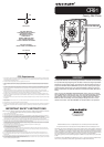
LOCATION OF PARTS
PARTS INDUDED
1
-
TELEPHONE HANDSET
1
-
TELEPHONE BODY
1
-
7 FOOT LINE CORD
1
-
15 INCH LINE CORD
1
-
DARK BROWN HANDSET CORD
2
-
SCREWS
WITH WALL ARCHORS
1
-
WALL MOUNTING TEMPLATE.
4
-
RUBBER SPACER PADS.
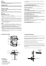
RINGER CONTROL HI
LOW
OFF
WALL
MOUNTING
HOLES
LINE CORD JACK
RECEIVER VOLUME HI
MID
LOW
DIAL MODE TONE
PULSE
LAST
NUMBER
REDIAL
HANDSET
CRADLE
HANDSET
HANDSET
CORD
HANDSET
CORD JACK
DESK LID
GRANK
HANDLE
DIAL
STORAGE
COMPARTMENT
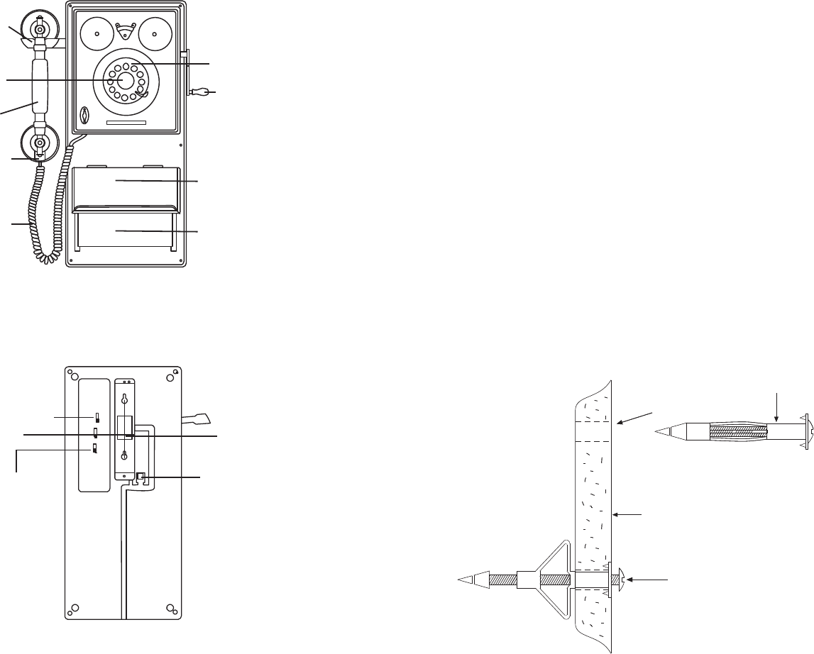
WALL
AFTER INSTALLATION
1/4" HOLE
WALL ANCHOR
PRIOR TO INSTALLATION
WALL
AFTER INSTALLATION
1/4" HOLE
WALL ANCHOR
PRIOR TO INSTALLATION
To Install Wall Anchors
If the location you have chosen to mount your telephone is a hollow wall without any
beams you will have to use the included wall anchors.
To install, place the template against the wall where you wish to place your telephone.
Mark the wall at the location of the two + on the template by pushing a pen or pencil
through the template. Drill a 1/4" hole at each mark.
Push the wall anchor into the hole and gently tap until it is flush with the wall.
With a phillips screwdriver, begin tightening the screw.
CLOCKWISE. Stop turning when you feel firm resistance.
Turn the screw counter clockwise until the screw head is about 1/4" out of the wall.
Install the 7 foot line cord at back of the telephone . Adjust the switches to your
preference. Position the line cord through the slot on the bottom of the cabinet. Line
up the holes with the two screws. Place the telephone onto these two screws and
gently pull down.
This may require a little fine tuning until the phone is seated securely.