


SET UP
DIAL MODE
Locate the DIAL MODE switch on the rear of the telephone body. Slide the switch to
TONE unless you have Dial-Pulse (Rotary) telephone service in your area in which case,
slide the switch to the PULSE position.
RINGER CONTROL
The RINGER CONTROL switch on the rear of the telephone body allows you to turn the
ringer OFF or set it to ring at either NORMAL or HIGH volume. You can still make or
receive calls with the ringer in OFF position, however, you will not hear the incoming
ring.
RECEIVER VOLUME
The RECEIVER VOLUME CONTROL switch, located on the rear of the telephone body,
allows you to adjust the volume of the receiver earphone from LO, MED and HI.
HANDSET CORD
To assemble, insert the end of the handset cord into the HANDSET CORD JACK located
on the left side of the telephone body.
INSTALLATION
MODULAR WALL JACK
To install the telephone directly on a modular wall jack :
1. Connect the 15 inch line cord to the LINE CORD jack on rear of telephone body.
2. Tuck the line cord into the channel on the back of the phone.
3. Peel and stick the rubber pads on the back side of the phone in the 4 corners.
4. Hold the telephone body up next to the modular jack and plug the line cord into this
jack.
5. Tuck the excess line cord into the recess provided on the back of the phone.
6. Line up the mounting holes of the telephone body with the mounting studs (screw
heads) on the modular jack or wall.
7. Push the telephone body against the wall jack and gently pull down.
WALL
If you are not mounting directly onto a modular wall jack, proceed as follows :
1. Install the 7 foot line cord into the LINE CORD jack on the back of the telephone. If
the desired location is farther than 7 foot from a wall jack, you will have to obtain a
longer line cord available at most hardware stores.
2. Place the provided TEMPLATE against the wall in the position desired.
3. Mark the wall by poking either a pen or pencil through the indicated spots on the
template.
4. If there is no stud at this location, it will be necessary to install the provided wall
anchors. Drill a small pilot hole at the marked locations. Tap the anchors into the
holes. Then insert screws, but DO NOT TIGHTEN. Leave the screw heads protruding
about ¼ inch.
5. If there is a stud at this location, simply install the two screws into the stud. REMEMBER,
leave screw head protruding.
6. Telephone is then mounted according to procedure detailed in MOUNTING TO
MODULAR PLUG.
NOTE : If you encounter difficulty fitting the telephone body onto the screws, or the
telephone wobbles when installed, either tighten or loosen the screws to adjust.
TABLE
1. Connect 7 foot line cord to LINE CORD jack on the rear of the telephone body.
2. Plug free end of line cord into nearest modular telephone jack.
MAKING AND ANSWERING CALLS
To get a dial tone or answer an incoming call, lift the handset.
To hang up, either replace the handset or simply press down the HANDSET CRADLE.
REDIAL
The last number dialed is automatically stored in the phone. To redial the last number,
lift the handset and press the REDIAL (coin release) button.
COINBOX
Coins can be deposited into the COIN SLOTS located on the top of the telephone body.
The coins will ring a bell and drop into the coin box. The coinbox may be opened by
inserting the key and rotating.
TROUBLESHOOTING
If you experience problems with your telephone, try the following suggestions:
NO DIAL TONE
1. Make sure that all plugs are connected properly. Check the connections at the wall
jack, the telephone body and the handset.
2. Try another modular jack within your home which you know to be working properly.
CALLS CANNOT BE DIALED OR DIALED SLOWLY
Check to make sure that the DIAL MODE switch is in the correct position for the type
of service available in your area.
TELEPHONE DOES NOT RING
Check that RINGER CONTROL switch is not set to OFF.
If there are several telephones connected to the same line, try disconnecting some of
the other telephones. Having too many telephones connected to the same line can cause
low ringer volume or poor sound quality during calls.
CARE AND MAINTENANCE
Avoid rough treatment to your telephone. Do not drop the handset and always replace
it gently onto the cradle.
Clean only with a cloth slightly dampened with water only. Do not use detergents, waxes,
solvents, sprays, alcohols or excessive water.
910-008800-008
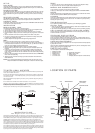
LOCATION OF PARTS
INSTRUCTION TO USE
FCC Registration Information
This equipment complies with Part 68 of the FCC rules. On the lower side of the equipment is a label
that contains, among other information, the FCC registration number and the Ringer Equivalence.
Number (REN) for this equipment. If requested, provide this information to your telephone company.
The REN is useful to determine the quantity of devices you may connect to your telephone line.
Excessive REN’s on the telephone line may result in the devices not ringing in response to an incoming
call. In most areas, but not all areas, the sum of the REN’s should not exceed five (5.0). To be certain
of the number of devices you may connect to you lines, as determined by the REN, you should call your
local telephone company to determine the maximum REN for your calling area.
If your telephone equipment causes harm to the telephone network, the telephone company will notify
you in advance that temporary discontinuance of service may be required. But if advance notice is not
practical, the telephone company will notify the customer as soon as possible. Also you will be advised
of your right to file a complaint with the FCC if you believe it is necessary.
WALL
AFTER INSTALLATION
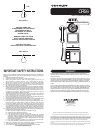
1/4" HOLE
WALL ANCHOR
PRIOR TO INSTALLATION
WALL
AFTER INSTALLATION
1/4" HOLE
WALL ANCHOR
PRIOR TO INSTALLATION
TO INSTALL WALL ANCHORS
If the location you have chosen to mount your telephone is a hollow wall without any beams you will
have to use the included wall anchors.
To install, place the template against the wall where you wish to place your telephone. Mark the wall
at the location of the two + on the template by pushing a pen or pencil through the template. Drill a
1/4" hole at each mark.
With a Phillips screwdriver, begin tightening the screw by turning it clockwise. Stop turning when you
feel firm resistance.
Turn the screw counter clockwise until the screw head is about 1/4" out of the wall.
Install the 7 foot line cord at back of the telephone . Adjust the switches to your preference. Position
the line cord through the slot on the bottom of the cabinet. Line up the holes with the two screws. Place
the telephone onto these two screws and gently pull down.
This may require a little fine tuning until the phone is seated securely.
TELEPHONE BODY
COIN BOX
HANDSET
DIAL
HANDSET
CRADLE
COIN SLOTS
REDIAL BUTTON
( coin release)
MOUNTING HOLES
RINGER
CONTROL
HI
LOW
OFF
DIAL
MODE
TONE
PULSE
CHANNEL
LINE CORD JACK
RECEIVER
VOLUME
HI
MED
LO
SPACE PADS
HEADSET
CORD JACK
PARTS INCLUDED
Your new telephone includes the following items:
1 - Telephone handset
1 - Handset coil cord
1 - Telephone body
1 - 7 Foot line cord
1 - 15 Inch line cord
2 -
Screws
with wall archors
4 - Rubber spacer pads.
2 - Tapping screw
1 - Template (See above picture and instructions)
HEADSET
CORD JACK
HANDSET
CORD