


INSTALLING YOUR T ELEPHONE
MODULAR JACKS
To install your telephone, you must have a modular wall jack
at the desired location, or a 4-prong jack that can be modified with
a 4-prong adapter. If your telephone line does not have a modular
wall jack, or a jack that can be modified, you must have one
installed.
DANGER: To reduce the risk of electrical shock
and personal injury, observe the following when
installing station wiring:
1. Never install telephone wiring during a
lightning storm.
2. Never install telephone jacks in wet locations
unless the jack is specifically designed for
wet locations.
3. Never touch uninsulated telephone wires or
terminals unless the telephone line has been
disconnected at the network interface.
4. Use caution when installing or modifying
telephone lines.
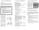
Various types of modular
wall jacks are shown to the
right. The USOC RJ11C
modular wall jack is for desk
telephones and the USOC
RJ11W modular wall jack is
for modular wall telephones.
The USOC RJ11W modular
wall jack must be in the
correct mounting position
before mounting a modular
wall telephone. Check to
make sure it is in the position
shown.
Various types of 4-prong
wall jacks are shown to the
right along with a 4-prong
adapter. The 4-prong
adapter plugs into the wall
jack for modular wall jack
service.
INSTALLING YOUR T ELEPHONE
TELEPHONE SERVICE PROBLEMS
If you have any problems with your telephone service,
determine if the problem is with your telephone or the telephone
company lines. BEFORE CALLING THE TELEPHONE COMPANY,
be aware that they may charge you for a service call if the
problem is caused by your telephone.
NO DIAL TONE
• Unplug your telephone from the wall jack. Plug a
substitute telephone that is known to work properly into
the same wall jack.
• If the problem persists when using the substitute
telephone, notify the telephone company.
• If the substitute telephone works properly, you must
have your telephone repaired before reconnecting it to
the wall jack.
DIAL TONE BUT NO RINGING
• Check that the RINGER VOLUME CONTROL is not set
to OFF.
• Set the RINGER VOLUME CONTROL to HIGH and
have someone on another line call you. Before
answering the call, set the RINGER VOLUME
CONTROL to the desired volume.
INSTALLING YOUR T ELEPHONE
DESK INSTALLATION
To install the Model 2500 desk
telephone, use the long modular
line cord supplied with your
telephone. Plug one end of the line
cord into the connector on the back
of your telephone and the opposite
end into the modular wall jack. Your
telephone is ready to use.
To disconnect your telephone, press the spring clip on the line
cord plug and pull out.
WALL INSTALLATION
To install a modular wall telephone,
refer to the diagram to the right.
• Fit the plug (1) on the back of the
telephone into the jack (2).
• Align slotted holes (3) on the
back of the telephone over the
mounting studs (4).
• Gently pull down on the tele-
phone until it locks in place.
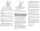
NUMBER CARD
Write or type correct telephone number on
number card and fit into number card slot
in the telephone faceplate. Insert one end
of the clear plastic retainer in one end of
the slot and, holding the retainer as shown
at right, bend the opposite end down into
the slot and let it snap into place. To
remove the retainer, insert a straightened
paper clip into the small slot in the retainer
and pry outward.
CHECK FOR DIAL TONE
Lift the handset and listen for dial tone.
• When you hear dial tone, your telephone is ready to use.
• If you do not hear dial tone, refer to the Telephone
Service Problems part of your manual.
SET THE RINGER VOLUME
If the ringer control is set to off to silence ringing, you cannot hear
the ringer when someone calls you. Move the control toward
LOUD to increase volume.
AW
90
-
59
RJ11C
RJ11W
MESSAGE WAITING LAMP WIRING
Wiring inside the telephone on
the networks PBA can be
changed to connect the
message waiting lamp across
the alternate BK/YL pair. (See
Table.) In this configuration
the message waiting lamp is
controlled on and off by the
connected equipment.
The telephone is shipped from the factory with the
message waiting lamp circuit connected across the Tip
and Ring (RD/GN) pair. In this configuration the message
waiting lamp is off when the handset is off-hook.
MESSAGE WAITING LAMP
CONDUCTOR CHANGES FOR
ALTERNATE BK/YL PAIR
2500 2554
FROM TO FROM TO
F
G
E1
L1
G
*GF2
(dial)
E1
L1
* Remove Dial PBA Strapping
Plug.