Customer Assistance WarrantyIntroduction Operation
Intro Operation Customer
Assistance
Warranty
Notice
Secondary Icons
Intro Operation Customer
Assistance
Warranty
Notice
Secondary Icons
Mode Functions and
General Specifications
Operation
Intro Operation Customer
Assistance
Warranty
Notice
Secondary Icons
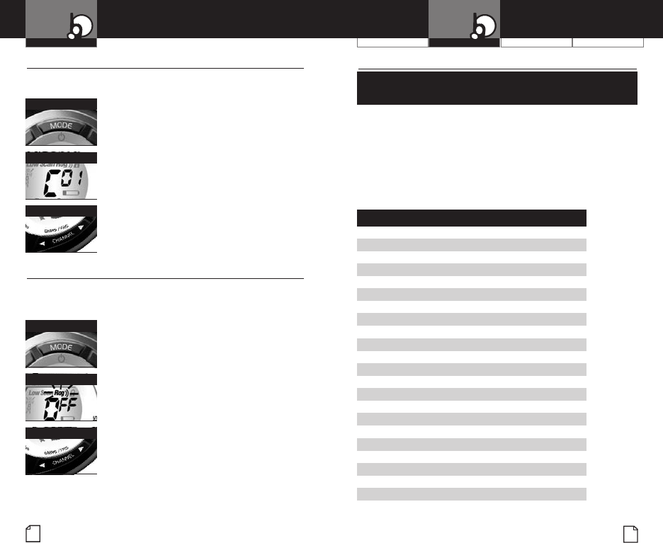
Five Call Tone Settings
•
You can choose between five different Call Tone Settings to
transmit a unique call alert.
To change a call tone setting:
1. Press the Mode/Power button until the
letter “C” and the current call tone number
(01 through 05) is displayed. The current
call tone will sound for one second.
2. Press the Channel Up or Channel Down
button to hear the other call tone settings.
3. Choose one of the following:
a. Press the Mode/Power button to
enter the new setting and proceed
to other functions.
b. Press the Lock button to enter the new
setting and return to
Standby mode.
Roger Beep Confirmation Tone
•
Your listener will hear an audible tone when you release the
Talk button. This alerts the other party that you are finished
talking and it is OK for them to speak.
To turn roger beep on or off:
1. Press the Mode/Power button until the
Roger Beep icon flashes. The current
on or off setting is displayed.
2. Press the Channel Up or Channel Down
button to select roger beep on or off.
3. Choose one of the following:
a. Press the Mode/Power button to enter the
new setting and return to
Standby mode
.
b. Press the Lock button to enter the new
setting and return to
Standby mode.
Call Tone Setting
M
ode/Power Button
Channel Button
Rog
er Beep Off
Mode/Power Button
Channel Button
English
12
13
Nothing comes close to a Cobra
®
General Specifications
•
FRS/GMRS Frequency
Allocation and Compatibility
Important: Please note that Cobra GMRS models with 15 Channels may
designate different channel numbers for the same frequency.For example,
a Cobra15 Channel GMRS model would need to be tuned to Channel 11
in order to communicate with a 22 Channel GMRS tuned to Channel 15.
Please refer to the chart below for channel/frequency number compatibility.
A = Channel No. for 22 Channel GMRS Models
B = Channel No.for 15 Channel GMRS Models
C =Type of Radio Service
D = Frequency in MHz
A B C D
1 1 FRS/GMRS 462.5625
2 2 FRS/GMRS 462.5875
3 3 FRS/GMRS 462.6125
4 4 FRS/GMRS 462.6375
5 5 FRS/GMRS 462.6625
6 6 FRS/GMRS 462.6875
7 7 FRS/GMRS 462.7125
8 FRS 467.5625
9 FRS 467.5875
10 FRS 467.6125
11 FRS 467.6375
12 FRS 467.6625
13 FRS 467.6875
14 FRS 467.7125
15 11 GMRS 462.5500
16 8 GMRS 462.5750
17 12 GMRS 462.6000
18 9 GMRS 462.6250
19 13 GMRS 462.6500
20 10 GMRS 462.6750
21 14 GMRS 462.7000
22 15 GMRS 462.7250


